You often face challenges when wiring an RJ45 Type B connection, especially if you mix up the wire sequence or fail to maintain consistent standards. Proper RJ45 termination preserves signal integrity and reduces electromagnetic interference, which can boost network speeds and minimize packet loss. Using the right Type B connector from a trusted Connector factory and testing each RJ45 connection helps you achieve reliable compatibility and performance. Excessive untwisting of pairs or poor crimping increases bit errors, while comparing RJ45 with an M8 connector highlights the importance of precise wiring in every connection.
RJ45 Type B and T568B Wiring Explained
What is RJ45 Type B?
You encounter RJ45 Type B as one of the two main rj45 wiring standards for Ethernet cabling. This standard, also called T568B, defines the color sequence and pinout for connecting twisted-pair cables to RJ45 connectors. When you use the T568B wiring standard, you ensure that your cables match the most widely adopted configuration in the United States. This standard supports the ethernet protocol and provides reliable connections for both commercial and residential network installations.
T568B Pinout and Color Code
Understanding the t568b pinout is essential for proper rj45 pin assignment. The T568B standard specifies the order of colored wires inside the connector. You must follow this sequence to avoid network issues and ensure compatibility with other devices.
Here is a comparison table showing the pin assignments for T568A and T568B:
| Pin Number | T568A Wire Color | T568B Wire Color |
|---|---|---|
| 1 | White/Green | White/Orange |
| 2 | Green | Orange |
| 3 | White/Orange | White/Green |
| 4 | Blue | Blue |
| 5 | White/Blue | White/Blue |
| 6 | Orange | Green |
| 7 | White/Brown | White/Brown |
| 8 | Brown | Brown |
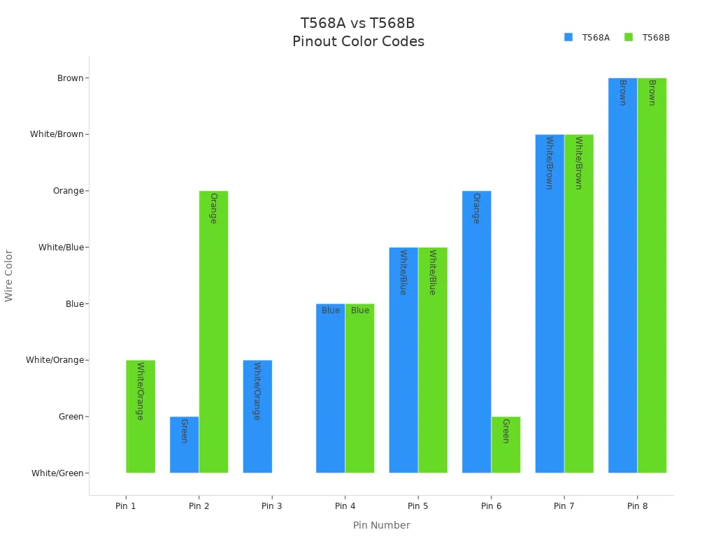
You notice that the main difference between T568A and T568B is the swapping of the green and orange pairs. The blue and brown pairs remain unchanged. Both standards use the same RJ45 connector and support the ethernet protocol at high speeds, including Gigabit Ethernet. The choice between T568A and T568B does not affect network performance, but you must use the same standard on both ends of a cable.
Why Choose T568B for Your Network?
You often select T568B because it is the prevailing standard in modern network installations, especially in the United States. This standard aligns with most contemporary equipment and is the default for many telecom and data center environments. When you use T568B, you simplify maintenance and ensure compatibility across your network.
Some common applications for T568B include:
- Ethernet networks in offices and homes
- Data centers for server connections
- VoIP phone systems using Ethernet technology
- Industrial automation systems in factories
T568B wiring also supports Power over Ethernet (PoE), which powers devices like security cameras and VoIP phones. You benefit from using T568B because it provides a consistent and reliable foundation for your network infrastructure. While T568A offers better backward compatibility with older telephone wiring, T568B remains the recommended choice for new installations due to its widespread use and support for modern ethernet standards.
Tip: Always maintain the same wiring standard throughout your network to avoid connectivity issues and ensure optimal performance.
Difference Between T568A and T568B
You often hear about the difference between t568a and t568b when setting up Ethernet networks. Both standards define how you arrange the colored wires inside an RJ45 connector. The main difference between t568a and t568b lies in the order of the green and orange wire pairs. This change does not affect Ethernet performance, but it does impact compatibility with legacy systems.
You should consider these points when choosing between the two standards:
- T568A matches older telephone wiring, making it ideal for residential or mixed-use installations.
- T568B is optimized for modern business networks and is the default in many commercial environments.
- T568A offers backward compatibility with legacy phone systems using RJ-11 plugs.
- T568B focuses on performance for Ethernet and is not backward-compatible with older phone wiring.
- Both standards work equally well for Ethernet devices, but you must keep the same standard on both ends of a cable.
Tip: Remember the mnemonic—“B for Business, A for Always-backward-compatible.” This helps you recall which standard fits your needs.
Consistency in your wiring standard prevents connectivity issues. You should always use the same standard throughout your installation.
T568A and T568B Standards in Practice
You see t568a and t568b standards used in different environments based on infrastructure and requirements. In the United States, T568B is the predominant standard for commercial and enterprise networks. Most new business installations default to T568B because it aligns with modern equipment and simplifies maintenance.
You find T568A more often in residential or government settings. ANSI/TIA recommends T568A for its backward compatibility with older USOC wiring schemes. This makes T568A suitable if you need to support legacy phone systems or mixed-use wiring.
Here is how you typically see these standards applied:
- T568B dominates commercial and enterprise installations.
- T568A appears in homes, government buildings, or where legacy infrastructure exists.
- No strict rule mandates one standard over the other. Your choice depends on existing wiring, regional preferences, or contract requirements.
- Consistency in your chosen standard is critical. Mixing standards within a network can cause signal loss or connectivity problems.
You should always match the standard to your environment and maintain it across all connections. This approach ensures reliable performance and avoids unnecessary troubleshooting.
Common Mistakes with RJ45 Type B (T568B) Wiring
Mixing Up Wire Order in T568B
Causes of Incorrect Wire Sequence
You may find that mixing up the wire order is one of the most frequent mistakes when working with RJ45 Type B. Many technicians confuse the orange and green pairs during installation. This confusion often happens because the color codes for T568B and T568A look similar at first glance. Rushing through the wiring process or not double-checking the pinout can also lead to errors. If you do not follow the correct sequence, your RJ45 connector will not match the T568B standard.
- Technicians frequently confuse the orange and green wire pairs in T568B installations, making this a common wiring error.
- Such wiring mistakes disrupt signal integrity, causing network slowdowns, outages, increased latency, and failures in device communication.
- Deviating from T568A or T568B standards leads to incompatible connections and bottlenecks, degrading network performance.
- Incorrect wiring complicates troubleshooting and can result in costly downtime and network outages.
- Proper adherence to wiring standards and careful wire management are critical to maintaining reliable network operation.
How to Prevent Wire Order Errors
You can prevent wire order mistakes by following a few best practices. Always use a clear wiring diagram for T568B and keep it visible at your workspace. Before inserting wires into the RJ45 connector, arrange them in the correct order and double-check each color. Take your time during the cabling process and avoid distractions. If you work in a team, communicate the chosen standard to everyone involved. Using a cable tester after termination helps you catch any errors before the cable enters service.
Tip: Lay out the wires flat and in order before inserting them into the connector. This step reduces the risk of crossing pairs and ensures a reliable RJ45 Type B connection.
Inconsistent Use of T568A and T568B Standards
T568A on One End, T568B on the Other
You might think that mixing T568A and T568B standards on different ends of a cable will not cause problems. In some cases, especially with modern Gigabit devices that support automatic crossover (MDI/MDIX), the network may still function. However, older or lower-speed devices often cannot handle this inconsistency. Using T568A on one end and T568B on the other unintentionally creates a crossover cable, which can disrupt communication between devices and complicate troubleshooting.
Mixing T568A and T568B wiring standards within the same network is not recommended despite identical transmission performance. Inconsistent use can cause connectivity issues, complicate network maintenance, and make troubleshooting more difficult. The main difference is the swapping of green and orange wire pairs; mixing them unintentionally can create crossover cables or mismatched wiring, disrupting network stability. Maintaining a consistent wiring code throughout the network is crucial to avoid performance problems and ensure seamless data transmission. Intentional mixing is only appropriate when creating crossover cables to directly interconnect devices without a switch or router. T568B is preferred for modern commercial networks, while T568A is often used for government or legacy systems, emphasizing the importance of consistency based on existing infrastructure.
Ensuring Consistency Across All RJ45 Connections
You should always choose one wiring standard for your entire network and stick with it. Consistency prevents confusion and reduces the risk of accidental crossovers. Label each cable and connector with the standard used, especially in larger installations. When you maintain the same standard, you simplify future upgrades and repairs. This approach ensures every RJ45 connection in your network supports reliable data transmission and minimizes downtime.
Note: Consistent use of T568B across all RJ45 connectors in your network infrastructure ensures compatibility and reduces troubleshooting time.
Poor Crimping of RJ45 Connectors
Signs of a Bad Crimp
You can spot a poorly crimped RJ45 connector by checking for loose wires, uneven pin heights, or cables that easily pull out of the connector. If you notice intermittent connectivity, frequent disconnects, or slow network speeds, a bad crimp may be the cause. Sometimes, you may see exposed copper or misaligned wires inside the connector. These signs indicate that the cable conductors do not make proper contact with the connector pins.
- Poor crimping causes weak or loose connections and misalignment of wires.
- Insufficient contact between cable conductors and connector pins leads to data transmission errors and intermittent connectivity.
- These issues result in increased latency, packet loss, and overall network instability.
- Damage to shielding integrity from poor crimping worsens electromagnetic interference (EMI), further degrading signal quality.
- Proper crimping techniques, adherence to wiring standards (T568A or T568B), and use of cable testers are critical to maintain reliable network performance and high data transmission rates.
Tips for Proper Crimping Technique
You can achieve a secure RJ45 connection by using the right tools and following a precise process. Always use a high-quality crimping tool designed for RJ45 connectors. Insert the wires fully into the connector, ensuring each conductor reaches the end of its channel. Apply firm, even pressure when crimping to guarantee solid contact between the cable and connector pins. After crimping, inspect the connector for proper alignment and test the cable with a network tester. This practice helps you catch any issues before the cable enters service.
Tip: Invest in quality RJ45 connectors and crimping tools. Reliable equipment reduces the risk of poor crimps and supports high-speed data transfer in your network.
Using the Wrong RJ45 Cable Type
Solid vs. Stranded Ethernet Cable
You face a critical decision when selecting the right Ethernet cable for your RJ45 connections. Solid and stranded cables serve different purposes in network installations. Solid Ethernet cables use a single copper conductor for each wire. This design delivers lower signal loss and better performance over long distances. You should use solid cables for permanent installations, such as in-wall cabling or backbone runs. These cables also support Power over Ethernet (PoE) applications effectively because they resist heat and environmental stress.
Stranded Ethernet cables, on the other hand, consist of multiple thin copper strands twisted together. This structure gives them flexibility and durability, making them ideal for patch cords and connections that require frequent movement. However, stranded cables experience higher attenuation, which means more signal loss over distance. They are less suitable for long runs or PoE applications due to their heat sensitivity.
The T568B wiring standard defines the arrangement and color coding of wire pairs inside the RJ45 connector. It does not change the electrical performance of the cable itself. Whether you use solid or stranded cable, T568B ensures consistent pairing and connectivity. The performance differences between solid and stranded cables remain the same regardless of the wiring standard you choose.
Note: Always match the cable type to your installation needs. Use solid cables for fixed runs and stranded cables for flexible patch cords.
Choosing the Right Cable for T568B Wiring
You must select the correct cable type to ensure reliable RJ45 connections and long-term network performance. Solid Ethernet cables excel in permanent installations. They provide stable connections and maintain signal quality over longer distances. Stranded cables work best for short patch cords and device connections where flexibility matters.
Using the wrong cable type does not directly harm network reliability if you maintain consistent T568B wiring on both ends. Problems arise when you mix wiring standards or perform improper terminations. Inconsistent wiring can cause intermittent connections and network failures. To maintain long-term reliability, always use the same wiring standard, terminate cables properly, and test each connection before deployment.
Tip: For backbone cabling or in-wall runs, choose solid Ethernet cable. For patch panels or device connections, use stranded cable for flexibility.
Neglecting Cable Testing After Termination
Why Testing RJ45 Type B Cables Matters
You cannot guarantee a reliable network without proper cable testing after termination. Even if your RJ45 connections look correct, hidden faults can cause slow speeds, dropped connections, or complete network failures. Testing verifies that each wire is correctly terminated and that the cable meets performance standards. Skipping this step can lead to hours of troubleshooting and costly downtime.
Cable termination and testing go hand in hand. You must confirm that every RJ45 cable supports the intended data rates and PoE requirements. Testing also ensures that the T568B wiring scheme is consistent on both ends, preventing connectivity issues.
Always test every Ethernet cable after termination. This step saves time and prevents future network problems.
Recommended Testing Tools and Methods
You should follow a systematic approach to cable testing after each RJ45 termination:
- Use a continuity tester immediately after crimping. This tool checks that all pins are properly connected and that the wiring is continuous.
- Employ a cable tester to confirm correct pin assignments and overall cable functionality. Many affordable models are available for both professionals and DIY users.
- Verify that the T568B wiring scheme matches on both ends of the cable. Inconsistent wiring can cause connectivity issues even if the cable passes a basic continuity test.
- Perform these tests before deploying the cable in your network. Early detection of faults prevents network disruptions and simplifies troubleshooting.
Note: Cable termination and testing are essential steps for every RJ45 installation. Never skip testing, even for short patch cords.
Excessive Untwisting of Pairs in T568B
Impact on Signal Quality and Performance
You must pay close attention to how much you untwist the wire pairs during RJ45 termination. Twisted pairs in Ethernet cables reduce electromagnetic interference and crosstalk. Excessive untwisting—more than 0.5 inch from the last twist to the contact point—disrupts the cable’s noise cancellation and impedance. This degradation weakens signal quality and can cause your network speed to drop from gigabit to 100 Mb/s. Even if the termination looks fine, excessive untwisting can result in unreliable or slow connections.
- Twisted pairs maintain signal integrity by minimizing interference.
- Untwisting beyond 0.5 inch degrades performance and disrupts noise cancellation.
- Signal quality drops, leading to slower or unstable network connections.
Best Practices for Pair Untwisting
You can maintain optimal signal quality by following these best practices during RJ45 termination:
- Untwist each pair only as much as needed to align the wires for insertion.
- Arrange the wires according to the T568B standard for correct data transmission.
- Trim the wires evenly, leaving about half an inch exposed for neat insertion.
- Use a load bar to keep conductors aligned before inserting them into the RJ45 connector.
- Keep the untwisted length tighter than the 0.5 inch ANSI/TIA specification whenever possible.
- Avoid kinking the conductors and ensure all wires make contact within 1/32 inch of the plug end.
- Crimp the connector firmly and evenly to prevent loose connections.
Tip: Maintain the twists as close to the RJ45 connector as possible. This practice preserves signal integrity and supports high-speed Ethernet performance.
Incorrect Cable Lengths and Routing for RJ45
Maximum Length Guidelines for T568B
You must pay close attention to the length of each ethernet cable when wiring your network with RJ45 connectors. The industry standard for T568B wiring sets a maximum recommended length of 100 meters, or 328 feet, for each cable run. This total includes up to 90 meters of fixed structured cabling, such as in-wall or ceiling installations, plus an additional 10 meters for patch cables at both ends. Both T568A and T568B wiring schemes share this limitation because they deliver identical electrical performance.
If you exceed the 100-meter limit, you risk signal degradation. The data may travel more slowly, and you could experience increased latency or even dropped connections. Overly long ethernet cable runs can also reduce data throughput, which impacts network efficiency and reliability. You should always measure your cable runs before installation and plan your network layout to stay within these guidelines.
Tip: Use a cable length tester to verify that your ethernet cable does not exceed the recommended maximum. This simple step helps you avoid costly troubleshooting later.
Avoiding Interference and Signal Loss
Proper routing of your ethernet cable is just as important as cable length. Poor routing practices can introduce interference and cause signal loss, even if you use the correct RJ45 wiring standard. You need to consider several factors to maintain optimal network performance:
- Over-tightening cable ties can damage the cable jacket and internal wires. This physical stress leads to intermittent connectivity and shortens the lifespan of your RJ45 cables.
- Routing ethernet cables too close to power lines or electronic devices increases the risk of electromagnetic interference. This interference degrades signal quality and can result in data packet loss.
- Using Velcro straps instead of plastic zip ties helps secure cables without applying excessive pressure. Velcro allows for easy adjustments and prevents crushing the cable.
- Maintain proper spacing between ethernet cables and sources of electrical noise. Avoid running cables parallel to power lines or near large electrical equipment.
- Bending cables beyond their specified limits introduces physical strain. Sharp bends or kinks disrupt the internal wire pairs, which negatively impacts signal integrity.
You should always plan your cable routes to minimize exposure to interference sources. Secure cables gently and avoid sharp turns. These practices help preserve signal quality and ensure your RJ45 connections deliver reliable performance.
Note: Careful cable management not only improves network reliability but also makes future maintenance easier. Organized routing reduces the risk of accidental damage during upgrades or repairs.
Step-by-Step Guide to Proper T568B RJ45 Wiring
Tools and Materials Needed for T568B
You need the right tools and materials to achieve a reliable T568B RJ45 wiring. Using quality equipment reduces errors and ensures each connector performs as expected. Here is a list of essential items for your installation:
- Select Ethernet cables (Cat5, Cat5e, or Cat6) that match your network requirements.
- Use a cable stripper to remove the outer jacket without damaging the internal wires.
- A wire cutter helps you trim wires evenly for a clean fit inside the RJ45 connector.
- Choose RJ45 connectors compatible with your cable type.
- A crimping tool secures the connector to the cable and ensures solid electrical contact.
- A punch-down tool is necessary if you terminate cables into keystone jacks or patch panels.
- A cable tester verifies the integrity of your finished cable and detects wiring faults.
- Optional items include strain relief boots for added protection and a punch-down stand for stability.
- Good lighting and an organized workspace help you avoid mistakes during the process.
Tip: Patience and precision are just as important as your tools. Take your time to ensure each step is correct for a resilient network setup.
Preparing the Ethernet Cable for RJ45
You must prepare the Ethernet cable carefully before attaching the RJ45 connector. Start by measuring and cutting the cable to your desired length. Use a cable stripper to remove about 1.5 inches of the outer jacket. Take care not to nick or damage the internal wires. Once you expose the twisted pairs, untwist them fully up to the jacket. Straighten each wire with your fingers to make the next steps easier.
Arrange the eight wires so they do not cross or tangle. Trim the wires evenly with a wire cutter, leaving enough length to reach the end of the RJ45 connector. If you use strain relief boots, slide them onto the cable before you begin stripping. This step prevents you from forgetting them later in the process.
Note: Always check the cable type and connector compatibility before starting. Using the wrong combination can cause connection failures.
Arranging Wires in T568B Order
You must arrange the wires in the correct T568B sequence to ensure proper data transmission. The T568B color code is as follows:
- White/Orange
- Orange
- White/Green
- Blue
- White/Blue
- Green
- White/Brown
- Brown
Lay the wires flat and align them in this order. Double-check the sequence before inserting them into the RJ45 connector. Straighten the wires and trim them again if needed, so they fit snugly into the connector slots. Insert the wires fully, making sure each one reaches the end of the connector. The cable jacket should also fit just inside the connector to provide strain relief.
Tip: Keeping the wires straight and in the correct order reduces the risk of wiring errors and improves the reliability of your RJ45 connector.
Inserting Wires into the RJ45 Connector
You need to insert the wires into the rj45 connector with precision. Begin by holding the connector so the clip faces away from you. Align the wires in the t568b order, keeping them flat and straight. Push each wire into its channel inside the connector. Make sure every wire reaches the front edge of the connector. If you see any wire falling short, remove them and trim again for a snug fit.
A good technique is to gently wiggle the wires as you insert them. This helps each conductor settle into its slot. The cable jacket should also slide slightly inside the connector body. This provides strain relief and protects the internal wires from bending or pulling. If you use a load bar, slide it over the wires before insertion. The load bar keeps the conductors aligned and makes the process easier.
Tip: Always double-check the wire order before inserting them into the rj45 connector. A quick glance at a color code chart can prevent costly mistakes.
Crimping the RJ45 Connector Securely
You must crimp the rj45 connector with care to ensure a reliable connection. Place the connector into the crimping tool, making sure it sits firmly in the slot. Squeeze the handles with steady pressure. The tool pushes metal contacts into each wire, creating a solid electrical connection. The crimp also locks the cable jacket in place, adding mechanical strength.
After crimping, inspect the connector closely. Look for even pin heights and check that no wires have slipped out. The rj45 connector should feel secure, with no loose movement. If you notice any issues, cut off the connector and repeat the process. Reliable crimping prevents intermittent network problems and supports high-speed data transmission.
A well-crimped rj45 connector reduces the risk of signal loss and ensures your network runs smoothly. Quality tools and connectors make a difference in the final result.
Verifying the T568B Pinout
You need to verify the t568b pinout after crimping the rj45 connector. This step confirms that each wire sits in the correct position and that the connector follows the t568b standard. Use a cable tester to check continuity on every pin. The tester identifies miswired pairs, shorts, and open wires. It also confirms that the color order matches the t568b scheme.
Keep a color code chart nearby during this process. Double-check the wire order before crimping to avoid errors. Testing with a cable tester ensures that your rj45 connector meets network standards and supports reliable data transmission.
- Use a cable tester to check each pin for continuity.
- Confirm the color order matches the t568b standard.
- Identify any miswired pairs, shorts, or open wires.
- Keep a color code chart at your workspace for reference.
- Double-check the wire order before crimping.
Note: Verifying the pinout after crimping saves time and prevents future troubleshooting. Reliable rj45 connector wiring supports stable network performance.
Testing the Finished RJ45 Type B Cable
After you complete the termination process, you must verify that your RJ45 cable works as expected. Proper testing ensures that every connection supports reliable data transfer and prevents frustrating network issues later. You should always follow a systematic approach to confirm both continuity and performance.
Start with a wire tester. This device checks continuity on all eight wires inside the RJ45 cable. Insert each end of the cable into the tester. The device will indicate if every pin connects correctly and if any pairs are miswired, shorted, or open. Continuity testing helps you catch wiring faults early, which saves time and effort during troubleshooting.
Next, connect the cable to a laptop or PC. Check if the network link establishes successfully. Most computers display the link speed—such as 10, 100, or 1000 Mbps—when you plug in the cable. This step confirms that the RJ45 cable supports the intended network performance. If you see a lower speed than expected, you may have a wiring or termination issue.
To further validate performance, transfer a large file between two devices or use a LAN speed test program. This real-world test reveals if the cable can handle sustained data transfer without errors or drops. If the transfer fails or the speed is much lower than expected, inspect your RJ45 termination and consider re-crimping the connector.
Tip: Do not rely solely on inexpensive testers. These devices may miss subtle faults that cause intermittent problems. Always combine basic continuity checks with real-world network tests.
If any test fails, re-terminate both ends of the cable using the correct T568B standard and a quality crimping tool. Make sure each wire seats fully and maintains its twist as close as possible to the connector. If problems persist after re-termination, replace the cable entirely. Consistency in wiring and careful attention to detail during each step of the process ensures optimal network performance.
Common issues you might encounter include intermittent operation, no connection, or connection drops when moving the cable. These problems often result from poor termination or damaged wires. Mastering RJ45 color coding and proper termination techniques helps you avoid these pitfalls.
Note: Always keep your cable runs within the 100-meter (328 feet) maximum length. Exceeding this limit can cause signal degradation and unreliable connections.
By following these testing steps, you guarantee that your RJ45 Type B cable delivers the performance and reliability your network demands.
Ensuring Compatibility and Network Performance with T568B
Matching T568B Standards Across Your Network
You ensure a reliable network connection when you match the T568B standard across your entire network infrastructure. Consistency in your wiring scheme prevents confusion and reduces the risk of signal errors. When you use T568B on both ends of every rj45 cable, you maintain correct signal pairing and avoid data loss or interference. This approach also preserves signal integrity and reduces electromagnetic interference, which is especially important in busy commercial environments.
- Consistent wiring order across all devices ensures correct signal pairing for smooth data transmission.
- Maintaining the same wiring standard (T568B) on both ends preserves signal integrity and reduces electromagnetic interference.
- T568B is preferred in commercial environments due to backward compatibility and better crosstalk performance.
- Using a single wiring standard simplifies installation, troubleshooting, and ensures compatibility, especially in mixed or legacy networks.
You benefit from easier troubleshooting and simplified network management. When you keep your wiring standard uniform, you avoid accidental crossover cables and ensure every connection supports your network’s performance needs.
Tip: Always label your cables and document your wiring scheme. This habit helps you maintain compatibility and makes future upgrades easier.
Device and Patch Panel Compatibility for RJ45
You must consider compatibility when connecting devices and patch panels using rj45 connectors. Both T568A and T568B use the same physical connector, but the wiring order differs. If you mix standards, you risk creating a crossover cable, which can disrupt your network connection unless your devices support auto-sensing. For best results, wire all patch panels and devices consistently with T568B. This practice avoids performance problems and ensures every connection works as intended.
Patch panels for rj45 ethernet connections support various cable categories, such as Cat5e, Cat6, or Cat6a. You should always match the cable category between your patch panel and your cables to maintain network performance. The number of ports and connection types should fit your network infrastructure needs. When you terminate cables on patch panels or devices, follow the same wiring standard on both ends. This rule applies to all cable categories and ensures proper network function.
Note: The physical connectors remain the same, so your main focus should be on consistent wiring and matching cable categories for full compatibility.
Backward Compatibility: T568A and T568B
You may need to upgrade or expand your network infrastructure. In these cases, backward compatibility becomes important. Both T568A and T568B support the same network speeds and reliability, but you must match the new cables to your existing wiring standard. Mixing T568A and T568B on the same cable creates a crossover cable, which can cause unintended issues and complicate troubleshooting.
- When upgrading or expanding a network, match new cables to the existing wiring standard to avoid confusion and network problems.
- Mixing T568A and T568B on the same cable creates crossover cables, which can cause unintended issues and complicate troubleshooting.
- Both T568A and T568B support the same network speeds and performance; the key factor is maintaining consistent wiring standards across all terminations.
- Consistency in wiring standards simplifies network management, reduces errors, and ensures reliability during upgrades.
- Proper documentation and labeling of wiring standards are essential to prevent mistakes during network expansions.
T568A wiring is backward compatible with some legacy systems, while T568B aligns with modern commercial infrastructure. For network upgrades, continue using your existing wiring scheme to maintain compatibility and avoid data loss or interruptions. Always document your wiring standards and label your cables to prevent mistakes during future expansions.
Avoiding Crossed or Split Pairs in RJ45 Wiring
When you wire an rj45 connector, you must pay close attention to the arrangement of the wire pairs. Crossed or split pairs are among the most common mistakes that can undermine your network’s reliability. These errors occur when you do not maintain the correct pairing of wires as defined by the T568B standard. Even if you follow the color code, you can still create a split pair if you do not keep the correct wires together as a pair.
Crossed pairs happen when you mix up the wiring schemes, such as using T568A on one end and T568B on the other. This mistake leads to incorrect pairing and disrupts the signal flow. Split pairs occur when you separate wires that should remain twisted together, such as failing to treat pins 3 and 6 as a pair. Both issues can cause serious problems for your rj45 connection.
If you create a split pair, you introduce interference and crosstalk into your network. This interference can cause data errors, voice call drops, and video glitches. You may notice slow speeds or unreliable connections, even if a basic continuity tester shows the cable as “good.”
You should understand the risks associated with crossed or split pairs in rj45 wiring:
- Split pairs cause crosstalk and signal delay, which degrade the quality of data, voice, and video transmission.
- Simple continuity testers often fail to detect split pairs, so you may not realize there is a problem until you experience network issues.
- Crossed pairs usually result from mixing wiring standards or swapping wire positions, leading to incorrect connections.
- Both crossed and split pairs reduce network performance and reliability, causing transmission errors and poor connection quality.
- Consistency in wiring schemes at both ends of the cable is essential to avoid these problems.
To prevent these issues, always use a proper wire map tester that checks for split pairs, not just continuity. Double-check your wiring against the T568B standard before crimping the rj45 connector. Keep the twisted pairs intact as close as possible to the connector to maintain signal integrity. When you finish a connection, test it with a device that can identify split pairs, not just basic faults.
| Problem Type | Cause | Impact on Connection | Detection Method |
|---|---|---|---|
| Crossed Pairs | Mixing wiring schemes or swapping wires | Incorrect signal flow, errors | Visual check, wire map |
| Split Pairs | Breaking up correct twisted pairs | Crosstalk, signal delay, poor data | Advanced cable tester |
Tip: Always match the wiring standard on both ends of every rj45 cable. This simple habit helps you avoid crossed pairs and ensures every connection supports reliable network performance.
By following these best practices, you protect your network from hidden faults and ensure every rj45 connection delivers the speed and reliability you expect.
Troubleshooting Checklist for RJ45 Type B (T568B) Wiring
Visual Inspection Steps for T568B
You can catch many wiring mistakes with a careful visual inspection before you test your rj45 connections. Follow these steps to identify common issues:
- Inspect each cable for physical damage. Look for cuts, fraying, or kinks that could affect performance.
- Examine the rj45 connectors. Check for looseness, dirt, or any visible damage that might disrupt connectivity.
- Confirm the wiring order inside every connector. Make sure the color sequence matches the T568B standard on both ends.
- Use the color-coded wires as a reference. Verify the correct pinout sequence according to T568B.
- After visual checks, use a cable tester to confirm wiring correctness, detect shorts, and check continuity.
- Ensure all cables are properly seated and connectors are fully crimped. This step maintains signal integrity.
- Organize your cable management. Prevent stress or bending that could cause wiring faults.
Tip: Consistent visual inspection helps you avoid costly troubleshooting later. Organized cables and clean connectors support reliable rj45 performance.
Testing for Continuity and Network Performance
You need to test each rj45 cable after visual inspection to ensure proper operation. Start with a cable tester to check for continuity. This device confirms that every wire connects correctly and that there are no shorts or open circuits. Next, test for network performance by connecting the cable to your devices. Observe if the link speed matches your expectations.
Common errors found during testing include line disconnection, short circuits, crossed wires, color inversion, and string winding. The table below summarizes these issues and their impact:
| Common RJ45 Type B Errors | Description | Impact on Network Performance |
|---|---|---|
| Line Disconnection | One or more core wires are disconnected at termination points. | Causes connectivity loss or intermittent connections. |
| Short Circuit | Core wires are unintentionally interconnected. | Leads to network failure; can be located using time domain reflection testing. |
| Crossed Wires | Wires are mixed up due to incorrect placement, often caused by similar wire colors. | Results in miswiring and connectivity issues. |
| Color Inversion | Using T568A on one end and T568B on the other, reversing wire pairs. | Causes improper signal transmission; not allowed in projects. |
| String Winding | Incorrect twisting of wire pairs, combining cores from different pairs. | Destroys twisted pair balance, causing network failure despite passing basic continuity tests. |
Note: Always use both basic continuity tests and real-world network performance checks. Some wiring faults only appear under actual data transmission.
Identifying and Fixing Common RJ45 Errors
You can resolve most rj45 wiring problems by identifying the root cause and applying the correct solution. Watch for these frequent issues:
- Intermittent cable operation or reduced speeds often result from wires not properly seated or excessive untwisting. Re-terminate the cable using the correct color scheme.
- No connection usually means the wrong color code pattern or crossed wires. Ensure you use the same standard, T568A or T568B, on both ends.
- Cable failure over longer runs may stem from poor termination or excessive untwisting. Keep wire twists tight near the connector.
- Connection drops when moving the cable often indicate a loose crimp or damaged cable. Re-terminate or replace the cable.
Other problems include crosstalk from tight bundling, interference from external sources, and connector issues from poor crimping. You can prevent these by maintaining proper cable management, using quality connectors, and keeping cables away from sources of electromagnetic interference.
Alert: Never ignore small faults. Even minor wiring errors can lead to major network disruptions.
When to Re-terminate or Replace a Cable
You often face a decision when troubleshooting RJ45 Type B (T568B) wiring: should you re-terminate the cable or replace it entirely? Making the right choice saves time, reduces frustration, and ensures your network remains reliable.
Re-terminate the Cable When:
- You spot a visible wiring error, such as incorrect color order or a misaligned pin.
- The cable fails a continuity or wire map test, but the cable jacket and conductors remain undamaged.
- You notice intermittent connectivity, and a visual inspection reveals loose or poorly crimped wires.
- The cable length fits within the recommended maximum, and the cable jacket shows no signs of wear or cuts.
- You see excessive untwisting near the connector, but the rest of the cable appears intact.
Tip: Always cut off the old connector and strip back to fresh wire before re-terminating. This step ensures a clean, reliable connection.
Replace the Cable When:
- The cable jacket has deep cuts, nicks, or abrasions that expose the internal wires.
- You find kinks, sharp bends, or crushed sections that may have damaged the twisted pairs inside.
- The cable fails multiple re-terminations or continues to show poor performance after testing.
- The cable run exceeds the 100-meter (328 feet) maximum, causing persistent signal loss or slow speeds.
- You detect corrosion, discoloration, or greenish residue on the copper conductors, which signals oxidation.
| Situation | Action | Reason |
|---|---|---|
| Incorrect pinout or loose wires | Re-terminate | Fixes wiring errors and restores connection |
| Damaged jacket or exposed wires | Replace | Prevents shorts and ensures safety |
| Cable fails after re-termination | Replace | Indicates deeper internal damage |
| Excessive cable length | Replace | Maintains signal quality and performance |
| Corroded or oxidized conductors | Replace | Ensures reliable electrical contact |
You should always test the cable after re-termination. If the cable still fails, replacement becomes the best option. Using a faulty cable can lead to network downtime, data loss, or even equipment damage.
Alert: Never ignore physical damage or persistent faults. Replacing a bad cable protects your network and saves time in the long run.
By knowing when to re-terminate and when to replace, you keep your RJ45 Type B wiring error-free and your network running smoothly.
Best Practices for Error-Free RJ45 Type B Wiring
Quick-Reference Do’s and Don’ts for T568B
You can avoid most wiring headaches by following a clear set of do’s and don’ts during every rj45 installation. These best practices for implementation help you maintain network reliability and reduce troubleshooting time.
Do’s:
- Always use a wiring diagram for the T568B standard. Keep it visible at your workspace.
- Double-check the wire order before inserting them into the rj45 connector.
- Use a quality crimping tool and ensure each connector is fully seated.
- Test every cable after termination with a cable tester.
- Maintain the twists in each pair as close as possible to the connector.
Don’ts:
- Do not mix T568A and T568B standards within the same network.
- Avoid excessive untwisting of wire pairs near the rj45 connector.
- Never force wires into the connector if they do not align properly.
- Do not exceed the maximum cable length of 100 meters.
- Avoid routing cables near sources of electrical interference.
Tip: Consistency and attention to detail during each step of the process prevent most rj45 wiring errors.
Here is a quick reference table for your workspace:
| Do’s | Don’ts |
|---|---|
| Use T568B diagram | Mix T568A and T568B |
| Test every cable | Exceed 100m cable length |
| Keep pairs twisted | Untwist wires excessively |
| Use quality tools | Force wires into connector |
Maintenance and Documentation Tips for RJ45
You need to maintain your rj45 network to ensure long-term performance. Regular inspection and documentation make future upgrades and repairs much easier.
- Inspect each rj45 connector for signs of wear, corrosion, or loose pins. Replace any damaged connectors immediately.
- Clean connectors with a soft, dry cloth to remove dust and debris.
- Check cable routing for sharp bends or kinks that could damage the internal wires.
- Use cable labels to identify each connection point. This practice helps you trace cables quickly during troubleshooting.
- Keep a logbook or digital record of your network layout, including cable lengths, connector types, and installation dates.
Note: Good documentation saves time when you expand or repair your network. You can quickly identify which cable or connector needs attention.
You should schedule periodic testing of all critical cables. Use a cable tester to verify continuity and performance. If you notice any drop in network speed or reliability, inspect the affected rj45 connector and cable immediately.
By following these maintenance steps, you extend the life of your network and reduce the risk of unexpected failures. Organized documentation and regular checks keep your rj45 installation running smoothly.
You avoid the most common RJ45 Type B mistakes by double-checking wire order, using consistent standards, and testing every connection. For reliable T568B wiring, always use quality tools and follow a clear wiring diagram. Maintain compatibility across your network by labeling cables and documenting your work.
Remember: Careful preparation and regular inspection keep your network running smoothly.
FAQ
What is the difference between T568A and T568B wiring?
You see T568A and T568B standards use the same connector but arrange the green and orange pairs differently. Both support Ethernet, but T568B is more common in commercial networks. Always use the same standard on both cable ends.
Can you mix T568A and T568B in the same network?
You should not mix T568A and T568B within the same network. Mixing standards causes connectivity issues and complicates troubleshooting. Stick to one wiring scheme for all terminations to ensure reliable performance.
How long can an RJ45 Ethernet cable be?
You can run an RJ45 Ethernet cable up to 100 meters (328 feet). This length includes patch cords and fixed cabling. Exceeding this limit leads to signal loss and slower network speeds.
Why does excessive untwisting of pairs matter?
You must keep wire pairs twisted as close as possible to the connector. Excessive untwisting increases electromagnetic interference and crosstalk. This weakens signal quality and reduces network speed.
What tools do you need for proper RJ45 termination?
You need a cable stripper, wire cutter, RJ45 connectors, crimping tool, and cable tester. These tools help you strip, arrange, crimp, and test cables for reliable network connections.
How do you test an RJ45 cable after termination?
You should use a cable tester to check continuity and pin order. Connect both ends to the tester and verify each wire matches the T568B standard. Real-world network tests confirm speed and reliability.
What happens if you use the wrong cable type?
You risk poor performance if you use the wrong cable type. Solid cables suit permanent runs, while stranded cables work best for patch cords. Match cable type to your installation for optimal results.