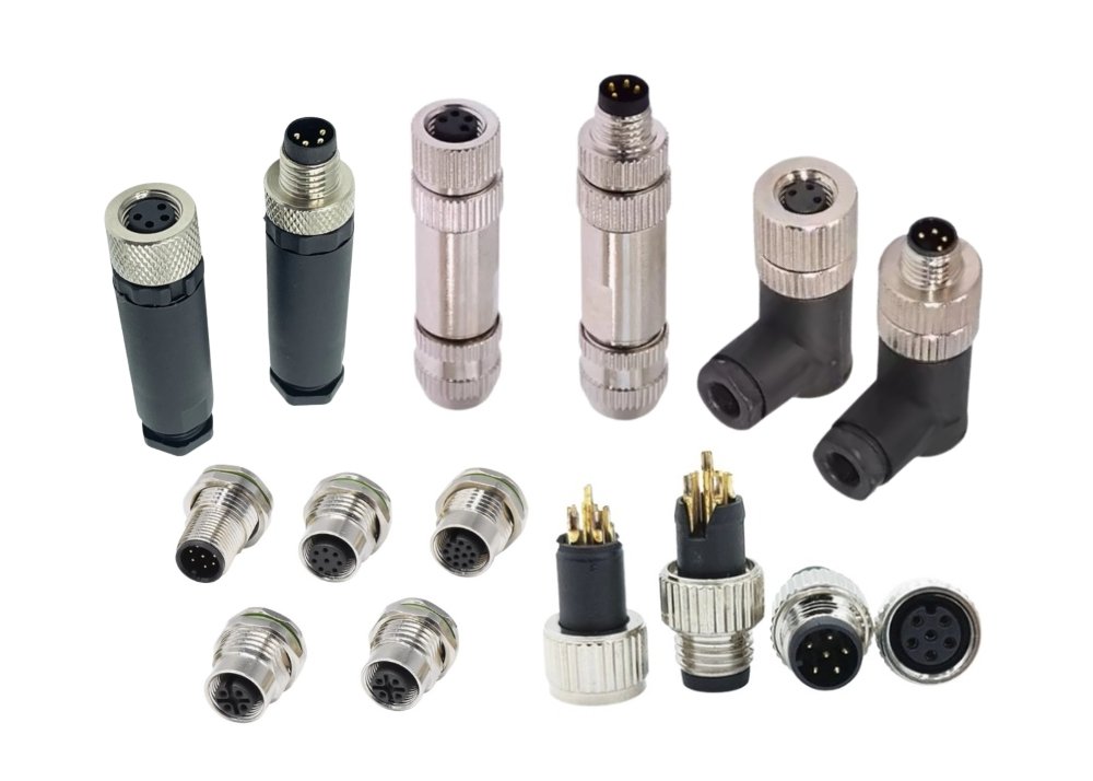
You often encounter wiring problems in 6-pin connectors, which can disrupt your equipment and compromise safety. When you inspect a connector, check the configuration for any signs of miswiring or loose contacts. Corrosion may appear, especially with an M8 connector or a Type B connector from a Connector factory. Quick detection and proper handling keep your systems running reliably.
6-Pin Connectors and Pin Configurations
Standard Pin Layouts for 6-Pin Connectors
Typical Pin Assignments in 6-Pin Connectors
When you work with 6-pin connectors, you often encounter different pin assignments based on the application. Each pin serves a specific function, such as carrying power, ground, or data signals. For example, in a 6-pin XLR connector, the pin assignments might look like this:
| Pin Number | Function |
|---|---|
| 1 | Ground |
| 2 & 3 | Balanced Audio |
| 4 & 5 | Additional Audio Channels or Power Lines |
| 6 | Auxiliary Data or Additional Power |
You should always check the documentation for your specific connector to confirm the correct configuration. Using the wrong pin assignments can cause device malfunctions or even permanent damage.
Color Coding Conventions for Pin Configurations
Manufacturers often use color coding to help you identify each wire’s function in a pin configuration. For instance, black usually represents ground, red indicates power, and other colors like blue, green, or yellow may signal data or auxiliary lines. However, color codes can vary between brands and industries. Always verify the color code with the wiring diagram before making any connections.
Tip: Never rely solely on color coding. Double-check the pinout diagram to avoid costly wiring mistakes.
Types of 6-Pin Connectors: 6-Pin XLR, Trailer, and Ebike Applications
Common Applications for 6-Pin Connectors
You will find 6-pin connectors in a wide range of equipment. Some of the most common uses include:
- Custom talkback systems in audio setups
- High-end or vintage microphones
- Specialized broadcast and film equipment
- Trailer wiring for lights and brakes
- Mid-tier e-bikes, especially those with detachable batteries
Each application may use a different pin configuration, so you must always confirm the wiring before connecting devices.
Connector Variations and Compatibility
Not all 6-pin connectors are created equal. You might see connectors that look identical on the outside but have different internal pin layouts. This can lead to compatibility issues and troubleshooting challenges. Consider these points:
- Identical-looking connectors may have different internal pin assignments.
- Understanding the wire functions for each pin is crucial for compatibility.
- Variations in pin layouts can cause incorrect connections and device malfunctions.
When you troubleshoot or replace a connector, always match both the physical connector and the internal pin configuration. This careful approach helps you avoid costly errors and ensures reliable operation.
Common Wiring Problems in 6-Pin Connectors
Pin Miswiring in 6-Pin Connectors
Symptoms of Pin Miswiring
Pin miswiring often leads to immediate and noticeable issues. You might experience devices failing to power on, erratic operation, or even overheating. In some cases, you may notice that certain functions do not work as expected, such as a missing audio channel or a non-responsive control. If you use a 6 pin jolet connector in an e-bike or similar application, incorrect pin assignments can prevent the system from starting or cause intermittent faults. Always pay attention to unusual behavior after installation or maintenance, as these can signal problems with the configuration.
Troubleshooting Pin Configuration Errors
To accurately diagnose pin miswiring, you should follow a systematic approach. The most effective diagnostic methods include:
- Use a multimeter to check electrical continuity and verify that each pin connects to its intended circuit. This tool helps you confirm that power and signals flow correctly through the pin configurations.
- Inspect the connector closely with a magnifying glass. This allows you to spot damaged, bent, or misaligned pins that could disrupt the wiring.
- Apply contact cleaner to remove debris or oxidation from the pins. Clean contacts ensure reliable conductivity and help you rule out contamination as a cause.
Tip: Always compare your findings with the official wiring diagram for your specific connector. This step helps you avoid confusion, especially when dealing with variations like the julet or other specialized connectors.
Loose or Poor Connections in 6-Pin Connectors
Identifying Loose Pins or Sockets
Loose connections can cause intermittent faults, signal loss, or complete device failure. You may notice flickering lights, unstable data transmission, or devices that only work when you wiggle the connector. To identify these issues, gently tug each wire and observe if any pins move or feel unstable. Check for sockets that do not grip the pins firmly. If you see any movement, you have likely found the source of the problem.
Corrective Actions for Connector Issues
You can address loose or poor connections by following these steps:
- Use proper installation techniques and the right tools to ensure each pin seats securely. Adhere to specified torque settings if your connector requires them.
- Employ locking mechanisms, such as screws or clips, to keep connectors firmly in place.
- Regularly inspect connectors for signs of wear or damage. Re-tighten connections as needed to maintain a secure fit.
- Replace connectors that show significant wear or cannot maintain a stable connection.
- Implement periodic maintenance checks to catch loose connections early.
- Use vibration-dampening mounts or fixtures to reduce the risk of connectors loosening over time.
Note: Secure connections are essential for both performance and safety. A loose connector can lead to overheating, arcing, or even fire hazards.
Corrosion and Contamination in 6-Pin Connectors
Signs of Corrosion in Connectors
Corrosion and contamination often appear as discoloration, green or white residue, or pitting on the metal surfaces of the connector. You may also notice increased resistance, unreliable operation, or a connector that feels gritty when you plug or unplug it. These symptoms indicate that moisture or debris has compromised the contact surfaces.
Cleaning and Prevention Steps for 6-Pin Connectors
To clean and protect your connectors, follow these recommended steps:
- Use isopropyl alcohol (IPA) to remove contaminants. IPA cleans effectively without damaging the connector materials.
- Apply a non-conductive brush or compressed air to dislodge particles from the connector. This method prevents accidental damage to the pins.
- After cleaning, allow the connector to dry completely before reconnecting.
- Store connectors in dry environments and use protective covers when possible to prevent future corrosion.
Callout: Regular cleaning and preventive care extend the life of your connectors and help maintain the correct pin functions of the 6 pin jolet connector.
By addressing these common wiring problems, you ensure that your 6-pin connectors deliver reliable performance and maintain safety in every application.
Signal Loss or Intermittent Connection in 6-Pin Connectors
Diagnosing Signal Issues in Pin Configurations
You may notice signal loss or intermittent connections in 6-pin connectors during equipment operation. These issues often present clear symptoms that you can identify with careful observation and basic diagnostic tools. Look for the following signs:
- Complete loss of power to certain components, such as lights or sensors.
- Random flickering of electrical systems, which may indicate a loose or corroded connector.
- Intermittent electrical failures, like inconsistent sensor readings or devices that work only when you move the connector.
- Visible damage, including cracks, corrosion, or bent pins.
- Loose fit, where the connector does not seat firmly.
- Unusual odors or excessive heat, which can signal electrical shorts.
You should use a multimeter to check for continuity across the pin configurations. A magnifying glass helps you inspect for bent or damaged pins. Contact cleaner removes debris that may interfere with signal transmission. These tools allow you to pinpoint the exact cause of the problem.
Solutions for Signal Restoration in Connectors
To restore signal integrity in your connector, you must address the root causes. Technical service bulletins highlight several leading causes of signal loss. The table below summarizes these causes and their explanations:
| Cause of Signal Loss | Explanation |
|---|---|
| Corrosion and oxidation | Moisture and contaminants can lead to corrosion of the connector’s metal surfaces, increasing resistance and potentially causing signal loss. |
| Poor contact pressure | Reduced contact pressure can lead to intermittent connectivity or signal degradation, especially in pin connectors. |
| Vibration and shock | Physical stress from vibrations can loosen connectors or damage internal contact points, leading to disconnects. |
| Improper handling or installation | Excessive force or incorrect alignment during installation can cause bent or broken pins, leading to failure. |
| Electrical overload | Exceeding current and voltage ratings can cause excessive heat, deforming the housing and damaging contacts. |
| Environmental factors | Extreme temperatures, humidity, and chemicals can degrade connector materials, impacting performance. |
| Insufficient connector quality | Low-quality connectors may fail prematurely due to poor materials and design, especially in demanding applications. |
| Mating misalignment | Misalignment during mating can lead to bent pins and broken contacts, affecting connectivity. |
To resolve these issues, follow these steps:
- Clean all contact surfaces using isopropyl alcohol and a non-conductive brush.
- Reseat the connector to ensure proper contact pressure.
- Replace any corroded or damaged pins.
- Secure the connector to prevent vibration-related loosening.
- Use only high-quality connectors that meet manufacturer standards, especially for critical applications like the 6 pin jolet connector or julet systems.
- Inspect for proper alignment before mating connectors to avoid bent pins.
Tip: Regular inspection and prompt repair of connectors help maintain signal integrity and ensure safety in your wiring systems.
Physical Damage to 6-Pin Connectors
Detecting Broken or Bent Pins in Connectors
Physical damage remains a common cause of failure in connectors. You should look for these signs during inspection:
- Melted plastic around the connector housing.
- Broken or bent pins inside the connector.
- Corrosion on metal contacts.
- Loose connections that do not hold firmly.
If you notice any of these issues, the connector may not function reliably. Melted plastic often results from electrical overload or poor contact, while bent pins usually occur from improper handling or misalignment during installation.
Repair or Replacement Procedures for 6-Pin Connectors
When you detect physical damage, you must decide whether to repair or replace the connector. Follow these recommended procedures:
- Replace broken pieces to fix bent pins or damaged parts.
- If you see extensive damage, such as melted plastic or multiple broken pins, replace the entire connector.
- Conduct electrical testing for continuity after any repair to confirm proper function.
- If the connector repeatedly disconnects or fails to maintain a stable connection, opt for replacement.
- Always choose connectors that meet the original equipment manufacturer’s standards for quality and safety.
Note: Using high-quality connectors and following proper installation techniques reduces the risk of physical damage and extends the life of your wiring systems.
Troubleshooting Process for 6-Pin Connectors: Step-by-Step Guide
Visual Inspection Techniques for 6-Pin Connectors
What to Look For in Pin Configurations
Begin your troubleshooting by examining the connector closely. Look for bent, broken, or missing pins in the pin configurations. Check for discoloration, residue, or signs of corrosion on the metal contacts. Inspect the housing for cracks or melted areas. If you see loose wires or pins that do not align with the configuration diagram, you may have a wiring issue. Confirm that the connector fits securely into its socket and does not wiggle when you move it.
Tools for Inspecting 6-Pin Connectors
You can improve your inspection with the right tools. Use a magnifying glass to spot small defects or contamination. A flashlight helps you see inside the connector housing. Tweezers allow you to gently adjust or remove debris from tight spaces. For advanced inspection, use a borescope to view hidden areas. These tools help you maintain safety and prevent damage during troubleshooting.
Using Testing Tools on 6-Pin Connectors
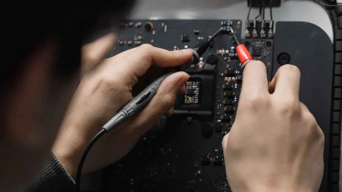
Multimeter Testing for Pin Configurations
A multimeter is essential for diagnosing electrical faults in 6-pin connectors. Set your multimeter to continuity mode. Connect the test leads to the relevant pins. If the circuit is complete, the multimeter emits a beep or shows low resistance. If you see ‘OL’ (open loop) on the display, the connection is broken. For short circuit testing, check between conductors that should remain separate. If you detect low resistance, a short exists and you must repair the wiring.
Continuity Checks for 6-Pin Connectors
Continuity testing confirms that each wire in the connector links to its intended point. Attach the multimeter leads to the test points. The meter sends a small voltage and measures resistance. High resistance signals a fault. If the circuit is intact, you hear an audible beep. For advanced diagnostics, use a four-wire milliohm meter to measure very low resistance. Values above 2.5 ohms may indicate poor connections, especially in a 6 pin jolet connector or julet system.
Tip: Always test each pin individually to ensure the entire connector functions as expected.
Systematic Correction Steps for Connector Issues
Rewiring Procedures for 6-Pin Connectors
If you discover miswiring or damaged wires, you must rewire the connector. Remove the faulty wires using a suitable extraction tool. Strip the wire ends to the correct length. Insert each wire into the proper pin location based on the configuration diagram. Use a crimping tool or soldering iron to secure the connection. Double-check your work before reassembling the connector housing.
Securing Connections in Pin Configurations
After rewiring, make sure all connections are tight. Use locking mechanisms, such as screws or clips, to prevent movement. Test the connector again with a multimeter to confirm proper function. For connectors exposed to vibration or harsh environments, consider using vibration-dampening mounts. Proper installation and regular inspection help maintain safety and extend the life of your connectors.
Troubleshooting Checklist for 6-Pin Connectors
Quick Reference Steps for Pin Configurations
A well-structured troubleshooting checklist helps you address wiring issues in 6-pin connectors efficiently. Use this quick reference to guide your process and minimize downtime.
Inspection Points for 6-Pin Connectors
Start with a thorough inspection. Focus on these critical points:
- Examine the connector housing for cracks, melted areas, or discoloration.
- Check each pin for signs of corrosion, oxidation, or residue.
- Look for bent, broken, or missing pins in the pin configurations.
- Ensure the connector fits snugly and does not wiggle when you move it.
- Inspect the locking mechanism or clips for damage or wear.
Tip: A visual inspection often reveals the root cause of many connector failures before you use any testing tools.
Testing Sequence for Connector Issues
After inspection, follow a systematic testing sequence to identify electrical faults. Use this ordered approach:
- Clean the connector using a contact cleaner and a soft brush. Remove all dirt and oxidation from the pins to ensure reliable contact.
- Test the connection with a multimeter. Check for proper power delivery and continuity across all pins. Confirm that each wire in the 6 pin jolet connector links to its intended circuit.
- Secure the fit of the connector. Make sure it seats firmly in its socket. Replace any broken or worn clips to maintain a stable connection.
- For julet connectors, verify that the alignment matches the manufacturer’s diagram. Misalignment can lead to intermittent faults or signal loss.
- Document your findings. Record any issues or repairs for future maintenance reference.
A clear testing sequence reduces the risk of overlooking hidden problems and ensures you address every potential fault.
Corrective Actions for Pin Configurations
Once you identify the issue, take corrective action to restore proper function:
- Rewire any misconnected or damaged wires according to the correct pin configurations.
- Replace corroded or broken pins with new components that match the original specifications.
- Tighten loose connections and secure the connector using locking mechanisms.
- Apply dielectric grease to the pins if the connector operates in a harsh environment. This step helps prevent future corrosion.
- Schedule regular maintenance checks to catch early signs of wear or contamination in connectors.
Regular maintenance and prompt corrective action extend the lifespan of your connectors and reduce the risk of unexpected failures.
A systematic checklist not only helps you resolve current issues but also supports long-term reliability for all your connectors.
Preventing Future Wiring Issues in 6-Pin Connectors
Installation Best Practices for 6-Pin Connectors
Proper Wire Stripping and Termination in Pin Configurations
You can prevent many wiring issues by following best practices for wire stripping and termination. Start by using a dedicated tool to strip about 2.5 inches of the cable jacket. Score the jacket gently to avoid damaging the conductors. Roll the cable to make it more circular before stripping. Straighten twisted wire pairs for better accuracy. Use pass-through RJ-45 connectors for easier wire management. Invest in a reliable crimping tool to achieve consistent results. Always test your connections with a cable tester to confirm proper pin assignment. For outdoor or high-moisture environments, utilize weather-resistant couplers and apply dielectric grease to protect the connector.
Tip: Wear a light work glove to protect your thumb and use a smooth shaft to straighten wires for a cleaner termination.
Secure Connector Mounting for 6-Pin XLR and Ebike Applications
Secure mounting is essential for both 6-pin XLR and ebike connectors. You should select robust connectors with seals and locking systems, especially for critical circuits. Avoid economy connectors in demanding applications. Route wires securely along factory paths and keep them away from sharp edges or moving parts. This approach prevents early failure and ensures plug-and-play compatibility. For ebike systems, proper mounting of the 6 pin jolet connector and julet connectors for ebikes supports reliable operation and reduces the risk of vibration-related faults.
| Installation Error | Prevention Method |
|---|---|
| Lack of training in wiring procedures | Ensure all technicians are trained in proper crimp techniques and connector assembly. Use hands-on demonstrations. |
| Failure to document modifications | Update wiring schematics and label changes immediately. |
| Use of improper terminals and connectors | Select robust connectors with seals and locking systems. |
| Improper routing of wires | Route wires securely along factory paths and avoid sharp edges or moving parts. |
Maintenance Tips for 6-Pin Connectors
Regular Inspection Schedule for Pin Configurations
Regular maintenance is key to long-term reliability. You should inspect connectors on a structured schedule, especially in high-use environments. This proactive approach helps you catch early signs of degradation and prevents costly downtime. Check for corrosion, loose pins, and damaged housings. Clean contacts as needed and replace worn components promptly. By following a routine, you ensure optimal performance and extend the lifespan of your connectors.
Environmental Protection Measures for Connectors
Environmental factors can cause corrosion and contamination in connectors. You can protect your connectors by choosing corrosion-resistant alloys like stainless steel or titanium. Avoid pairing dissimilar metals to prevent galvanic corrosion. Apply protective coatings such as nickel, gold, or tin electroplating. Use organic coatings like epoxy for a moisture barrier. Advanced self-healing coatings can repair minor damage automatically. Design connectors with minimal gaps and ensure proper ventilation to reduce moisture buildup. Control humidity and clean connectors regularly to maintain their integrity.
| Strategy | Description |
|---|---|
| Material Selection | Use corrosion-resistant alloys like stainless steel, titanium, and certain aluminum alloys. |
| Avoidance of Dissimilar Metals | Prevent galvanic corrosion by avoiding pairing dissimilar metals or using insulating barriers. |
| Protective Coatings | Apply coatings like nickel, gold, or tin electroplating to shield connectors from corrosion. |
| Organic Coatings | Use epoxy or polyurethane coatings to create a moisture barrier. |
| Self-Healing Coatings | Advanced coatings that repair themselves when damaged. |
| Design Considerations | Design connectors with minimal gaps and proper ventilation to reduce moisture buildup. |
| Environmental Controls | Control humidity and perform regular cleaning to prevent corrosion. |
Callout: Following installation and maintenance tips, such as these best practices for managing ebike connectors, helps you realize the advantages of using julet connectors. You gain reliable plug-and-play compatibility and reduce the risk of future wiring issues.
You ensure long-term reliability when you troubleshoot 6-pin connector wiring issues systematically. Following best practices and regular maintenance prevents future problems. Industry studies highlight several benefits:
- Regular inspections catch wear early and prevent failures.
- Cleaning and applying dielectric grease protect against corrosion.
- Organizing and labeling connectors avoids installation errors.
You can also enhance your skills through specialized training, such as the Datalink J1939/J1708 Troubleshooting course. Prompt repairs and inspections keep your equipment safe and operating at peak performance.
FAQ
What tools do you need to test a 6-pin connector?
You need a multimeter for continuity and voltage checks. A magnifying glass helps you inspect pins. Use contact cleaner for cleaning. For advanced diagnostics, use a milliohm meter.
How often should you inspect 6-pin connectors?
You should inspect connectors every three to six months in high-use environments. For outdoor or critical systems, check monthly. Regular inspection helps you catch early signs of wear or corrosion.
Can you repair a bent pin, or should you replace the connector?
You can gently straighten a slightly bent pin with tweezers. If the pin breaks or the connector housing is damaged, replace the connector to ensure reliable operation.
What causes intermittent faults in 6-pin connectors?
Intermittent faults often result from loose pins, corrosion, vibration, or misalignment. You may notice flickering lights, unstable signals, or devices that work only when you move the connector.
How do you prevent corrosion in 6-pin connectors?
Apply dielectric grease to the pins. Store connectors in dry environments. Use protective covers and select connectors with corrosion-resistant materials. Clean contacts regularly to prevent buildup.
Are all 6-pin connectors compatible with each other?
No, not all 6-pin connectors are compatible. You must match both the physical connector and the internal pin configuration. Always check the wiring diagram before connecting devices.
What is the safest way to disconnect a 6-pin connector?
Power off all equipment before disconnecting. Grip the connector housing, not the wires. Pull straight out to avoid bending pins. Inspect both sides for damage after removal.
Why is color coding not always reliable for wiring?
Manufacturers may use different color codes. Always verify with the wiring diagram. Relying only on color can lead to miswiring and equipment failure.