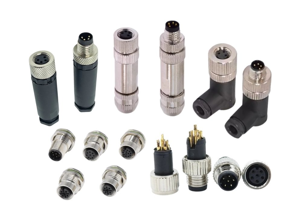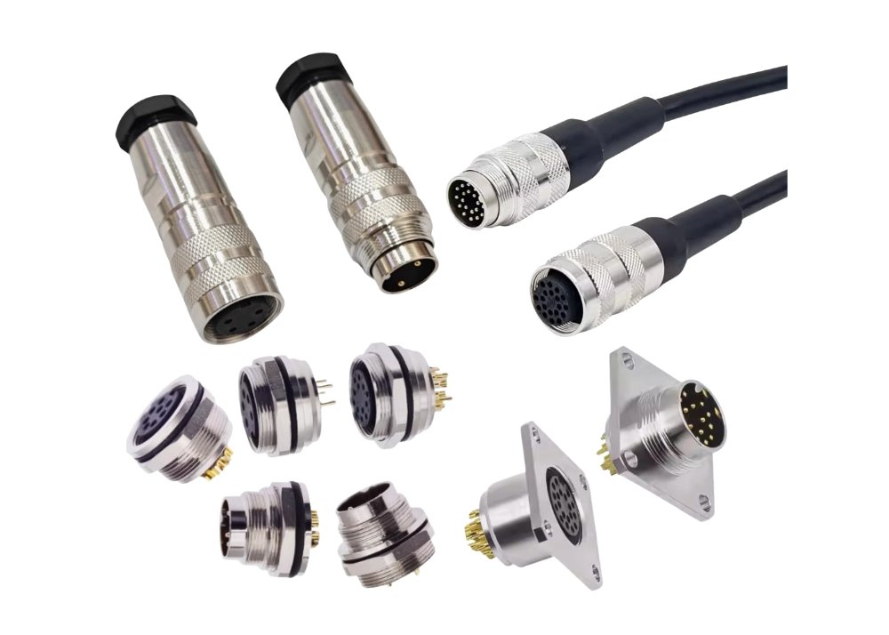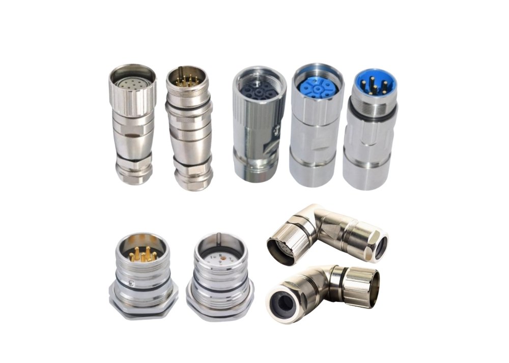
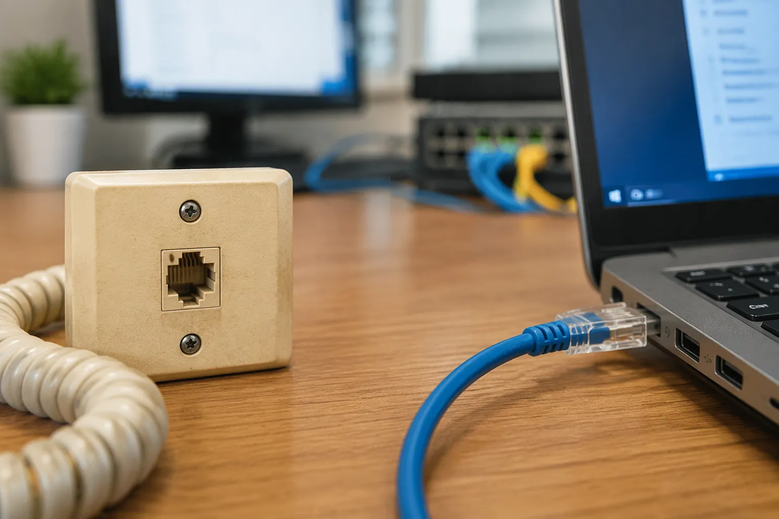
That familiar click signals a connection made millions of times a day. The rj-45 connector snaps into a port, and a device joins the network. This small part began as a telephone wiring interface. It now anchors Ethernet links across homes, offices, and data centers. Few people question how a telephone jack became the standard for wired networking. The rj45 name appears on countless cables, while rj-45 connector technology underpins global data traffic. Engineers also work with the M8 connector, the Type B connector, and every Connector factory that builds these parts. One question remains: how did a voice-era jack win the data era?
The Birth of the Registered Jack

The Registered Jack System Explained
Origins in Telephone Regulation
The registered jack system grew out of a regulatory need. In the early 1970s, the Bell System controlled nearly every telephone in the United States. Customers rented their phones from the phone company. They could not attach third-party equipment to the network. The Federal Communications Commission changed that arrangement with the Carterfone decision in 1968. The ruling allowed outside devices to connect to the public telephone network. A new problem appeared almost immediately. How could the industry guarantee that any approved device would plug safely into any wall outlet?
The answer came through a formal registration process. The FCC asked telephone companies and equipment makers to submit connector designs for review. Each approved design received a registration number. The system gave manufacturers a common target. A phone built in one factory could plug into a jack installed in another state. The registered jack was born as a regulatory tool, not an engineering experiment.
The Meaning of “RJ” Designations
The letters “RJ” stand for registered jack. Each designation carries a specific code. The first digit describes the number of wire positions. The second digit describes the number of wires actually connected. This coding scheme gave the industry a precise vocabulary. An RJ-11 jack, for example, uses six positions and carries two or four wires. The table below shows how several common designations compare.
| Designation | Positions | Wires Used | Typical Role |
|---|---|---|---|
| RJ-11 | 6 | 2 or 4 | Single-line voice |
| RJ-14 | 6 | 4 | Two-line voice |
| RJ-25 | 6 | 6 | Three-line voice |
| RJ-45 | 8 | 8 | Voice and data |
The designations describe wiring arrangements, not physical shapes. Two jacks can share the same plastic housing and still carry different RJ codes. This distinction matters for anyone who studies the history of the rj45 name. The label refers to a wiring pattern first, and popular usage later attached it to a physical connector.
The Original 8P8C Design
Anatomy of the Eight-Position Connector
The physical connector behind the RJ-45 designation is the 8P8C module. The name breaks down into three parts. The “8P” means eight positions. The “8C” means eight contacts. A molded plastic body holds the contacts in a single row. A small latch on top locks the plug into its jack. Gold plating covers the contact surfaces to resist corrosion. The plug measures roughly 11.7 millimeters wide, a size that fits comfortably in the hand.
The jack side mirrors the plug. Eight spring-loaded wires press against the plug contacts when the two halves meet. A keying tab prevents upside-down insertion. This mechanical design is simple, cheap, and repeatable. Those three qualities explain much of its long survival.
Why Eight Contacts and Eight Positions
Eight positions offered room to grow. Telephone engineers in the 1970s saw demand for more lines per outlet. Four wires handled two voice lines. Six wires handled three. Eight wires opened the door to four lines or to mixed voice and data service. The extra contacts also improved mechanical balance. A wider plug seats more evenly and resists rocking inside the jack.
The design team could have chosen six positions and saved material. They chose eight instead. That decision looked modest at the time. Decades later, it gave Ethernet engineers exactly the conductors they needed. Every twisted-pair Ethernet standard from 10BASE-T onward relies on four wire pairs. The eight-position layout maps perfectly onto that requirement.
RJ-45 in Telephone Networks
Early Voice and Data Wiring Roles
Telephone companies adopted the 8P8C connector for multi-line business service. A single wall outlet could feed four separate phone lines. Key telephone systems used these jacks to route calls between desks. The same connector also carried early data signals. Banks and airlines leased dedicated lines for terminals and modems. Those links often ran over the same twisted-pair cabling as voice service.
The connector’s dual role took shape in this period. It handled voice traffic and low-speed data at the same time. Engineers learned to separate the two services through careful wiring practices. This experience with shared cabling laid groundwork for the networking revolution that followed.
The Naming Confusion Around RJ-45
The name RJ-45 carries a technical inaccuracy. The true RJ-45 registered jack specifies a single data line on specific pins. The eight-position connector most people call RJ-45 does not match that specification exactly. Strictly speaking, the physical connector is an 8P8C module. The industry adopted the RJ-45 label anyway. It was short, familiar, and easy to say.
This loose naming persists today. Manufacturers, installers, and network engineers all use the term without hesitation. The rj-45-type connector sold in stores is an 8P8C plug in all but name. The confusion causes occasional friction in formal documentation. In practice, the meaning is clear from context. The label survived because it worked, not because it was precise.
From Voice to Data
The Rise of Ethernet
Early Ethernet and Coaxial Cabling
Ethernet began in the 1970s at Xerox PARC. Robert Metcalfe and his colleagues designed a system to link computers across a building. Their first network ran over coaxial cable. A thick yellow cable served as a shared bus. Every machine tapped into that bus through a vampire tap or a transceiver. The design worked well for a small campus. It delivered data at roughly 3 megabits per second.
The early Ethernet standard, published in 1980 and refined by the IEEE 802.3 working group in 1983, kept coaxial cable at its core. Thicknet gave way to thinner, cheaper cable known as Thinnet. Both designs shared one weakness. A single break in the bus could bring down the entire segment. Installers also struggled with the rigid cable and the bulky connectors. Offices needed a simpler wiring scheme.
The Shift to Twisted-Pair Wiring
Telephone wiring offered an obvious alternative. Buildings already contained miles of twisted-pair cable for voice service. That cable was cheap, flexible, and easy to pull through walls. Engineers at Bell Labs and elsewhere began testing data transmission over ordinary telephone wire. The results surprised many skeptics. Twisted pairs could carry high-speed signals over short distances with proper design.
The shift required new thinking about network topology. Instead of a shared bus, twisted-pair Ethernet used a star layout. Each device connected to a central hub. This arrangement simplified troubleshooting and isolated faults. It also matched the existing telephone cabling in most buildings. The stage was set for a connector that already lived on those wires.
Why RJ-45 Became the Ethernet Standard
Cost, Simplicity, and Compatibility
The 8P8C connector won the Ethernet race for practical reasons. It cost only pennies to manufacture. Crimping tools were inexpensive and widely available. Technicians already knew how to terminate telephone jacks. That existing skill base lowered training costs for network installers. The connector also fit the four-pair cable that twisted-pair Ethernet required.
The backward-compatibility of the rj-45 connector played a decisive role. Buildings wired for voice could often support data with minimal changes. The same wall outlets and patch panels served both purposes. This electrical and mechanical compatibility saved building owners enormous retrofit costs. A network upgrade became a matter of swapping electronics, not rewiring the walls.
Standardization Across the Industry
Standards bodies locked in the connector’s position. The IEEE 802.3 specifications defined how Ethernet signals travel over twisted pairs. The TIA/EIA-568 commercial cabling standard defined the pin assignments and performance requirements. These documents gave manufacturers a common target. A plug from one vendor would mate with a jack from another. Buyers gained confidence that their investments would interoperate.
Standardization and compatibility reinforced each other. Each new Ethernet speed built on the same physical interface. The industry could raise data rates without changing the connector on the wall. That continuity protected decades of installed cabling. It also gave the rj45 plug a permanence that few other connectors have achieved.
The Connector’s Early Data Milestones
10BASE-T and the First Mainstream Adoption
The IEEE approved 10BASE-T in 1990. This standard carried Ethernet at 10 megabits per second over two pairs of unshielded twisted-pair cable. It limited cable runs to 100 meters. The specification used the same 8P8C connector that telephone installers already stocked. Adoption spread quickly through offices. Network interface cards became standard equipment on business computers.
10BASE-T marked the moment when the rj-45-type connector became a networking fixture. Home users followed a few years later. Retail stores began selling patch cables and crimping kits to consumers. The click of a network cable became a common sound in homes and small businesses.
Establishing the Pinout Conventions
Early installations exposed a problem. Different vendors assigned signals to different pins. A cable wired by one company might fail when plugged into another company’s equipment. The industry needed a shared map. TIA/EIA-568 resolved the issue with two wiring schemes, T568A and T568B. Both schemes define which wire color lands on which pin.
| Pin | T568A Wire Color | T568B Wire Color | Signal |
|---|---|---|---|
| 1 | White/Green | White/Orange | Transmit + |
| 2 | Green | Orange | Transmit − |
| 3 | White/Orange | White/Green | Receive + |
| 4 | Blue | Blue | Unused (10/100) |
| 5 | White/Blue | White/Blue | Unused (10/100) |
| 6 | Orange | Green | Receive − |
| 7 | White/Brown | White/Brown | Unused (10/100) |
| 8 | Brown | Brown | Unused (10/100) |
The two schemes differ only in the swap of the orange and green pairs. Either scheme works as long as both ends of a cable match. A cable with T568A on one end and T568B on the other becomes a crossover cable. Early networks used crossover cables to link switches directly. Modern equipment detects the wiring automatically and adjusts.
These pinout conventions gave installers a reliable recipe. They also preserved backward-compatibility across generations of equipment. A cable wired to T568B in 1995 still carries gigabit ethernet traffic today. The pin assignments for 1000BASE-T use all four pairs, and the original eight-contact layout accommodates them without modification. That foresight turned a telephone-era design into a durable networking asset. The existing modular (rj-45) connectors on millions of walls needed no replacement as speeds climbed. Twisted-pair ethernet grew from a laboratory curiosity into the dominant LAN technology, and the connector grew with it.
Keeping Pace with Ethernet Speeds
The Fast Ethernet Era
100BASE-TX and Category 5 Cabling
The IEEE ratified 100BASE-TX in 1995. This standard pushed Ethernet to 100 megabits per second over two pairs of Category 5 cabling. Installers welcomed the news. Category 5 cable was already common in new office builds. The same 8P8C plug handled the higher speed without a physical change. Fast Ethernet turned the connector into a long-term infrastructure investment.
Growing Demands on Connector Quality
Higher frequencies exposed weaknesses in cheap components. At 100 MHz, poor terminations caused signal reflections and dropped packets. Manufacturers responded with tighter tolerances and better molding. Connector quality moved from an afterthought to a purchasing criterion. Buyers began to check performance ratings before ordering parts.
Gigabit and Beyond
1000BASE-T and Category 5e
Gigabit ethernet arrived in 1999. The 1000BASE-T standard used all four wire pairs and demanded cleaner signal paths. Category 5e cabling met that demand with improved crosstalk performance. The enhanced cable kept backward-compatibility with existing Category 5 installations. Networks could upgrade electronics without replacing wall wiring.
10GBASE-T and Category 6/6A
10 gigabit ethernet raised the bar again. The 10GBASE-T standard required category 6 (class e) cabling at minimum for short runs. Longer reaches called for class e (category 6) cabling with tighter specs or cat6a cable. Cat6a extended 10GBASE-T to the full 100-meter channel. These cable standards gave designers clear guidance for each distance.
Design Refinements for Higher Performance
Shielding and Crosstalk Control
Noise control became central as speeds climbed. Designers added foil and braid shields to block external interference. Pair separators inside the plug reduced crosstalk between conductors. These refinements let cabling carry fragile high-frequency signals with fewer errors.
Contact Plating and Durability Improvements
Contact surfaces also evolved. Gold plating thickness increased to survive more mating cycles. Hardened plastics resisted latch breakage during repeated insertion. Today’s connectors endure thousands of plug cycles in demanding environments. The humble plug now meets standards that its telephone-era designers never imagined.
RJ-45 Connector Technology in the Modern World
Where RJ-45 Lives Today
Enterprise and Data Center Networks
Large organizations depend on rj-45 connector technology every day. Office buildings run thousands of links through structured cabling systems. Each desk, printer, and access point connects through a modular (rj-45 style) connector. Data centers pack dense rows of switches and servers. These facilities use the same plug for management ports and server links. The connector’s low cost and reliable mating keep it central to enterprise design.
Home Networking and Consumer Devices
Homes rely on the rj45 plug for routers, smart TVs, and gaming consoles. Internet service providers ship gateways with four or more LAN ports. Consumers plug in a cable and gain a stable connection. Wi-Fi handles mobility, yet wired links remain the choice for speed and reliability. Streaming boxes and network storage drives often include an Ethernet port for this reason.
Power Over Ethernet
How PoE Expanded the Connector’s Role
Power over Ethernet changed what a network cable can do. The technology sends electrical power alongside data over the same twisted pairs. IEEE 802.3af introduced the first standard in 2003. Later revisions raised the power budget for larger devices. This capability removed the need for a separate power outlet at each device location.
Devices Powered Through RJ-45
Many devices now draw power directly through the connector. IP cameras mount on ceilings where outlets are scarce. Wireless access points receive both data and power from a single cable. VoIP phones, access control readers, and digital signage all rely on this arrangement. Installers save time and material on every PoE deployment.
Related Connector Variants
Shielded and Industrial Versions
Standard plugs suit office environments. Industrial settings demand more. Shielded versions add metal housings that block electromagnetic interference. Ruggedized plugs use metal latches and sealed bodies. These variants survive vibration, moisture, and temperature swings on factory floors.
Keystone Jacks, Pass-Through Plugs, and Field-Terminable Connectors
Installers choose from several termination styles. Keystone jacks snap into wall plates and patch panels. Pass-through plugs let wires exit the front during crimping, which reduces miswiring. Field-terminable connectors allow tool-free assembly on site. Each style supports the same gigabit ethernet signals and fits the same ports. Proper termination keeps cabling performance within standards and preserves signal integrity across the channel.
Standards and Specifications
The Governing Bodies
TIA/EIA and ISO/IEC Standards
Several organizations shape the rules for network cabling. The Telecommunications Industry Association and the Electronic Industries Alliance publish the TIA/EIA-568 documents. These documents serve as the industry standard for structured cabling in North America. The International Organization for Standardization and the International Electrotechnical Commission issue the ISO/IEC 11801 family. Together, these bodies define design, planning, installation, and field-testing standards for copper and fiber systems. Their work keeps u.s., international, and european standards aligned closely enough for global projects.
IEEE Ethernet Specifications
The IEEE 802.3 working group defines how Ethernet signals travel over each medium. Its specifications set data rates, encoding schemes, and reach limits. The IEEE documents reference the cabling technology and standards published by TIA and ISO. This division of labor lets each group focus on its own expertise. One group defines the electronics, and the other defines the physical layer.
Cabling Categories and the Connector
Category 5e Through Cat6a
Cable categories describe performance, not shape. Every category from 5e upward uses the same eight-position interface. A category 6 rj-45-style connector must meet tighter crosstalk limits than a Category 5e part. Class e (category 6) cabling supports 10GBASE-T to 55 meters. Cat6a extends that reach to the full 100-meter channel. Installers match the plug to the cable rating, because a weak connector drags the whole channel down.
Cat8 and Matching Connectors to Cable Ratings
Cat8 targets short data center runs at 25 and 40 gigabits per second. These cable standards cap distance at 30 meters. Cat8 requires shielded construction and careful grounding. A Cat8 cable paired with a lesser plug loses its rating. Network patch cable standards therefore tie connector performance to cable class. Buyers should treat the plug and the cable as one certified unit.
Testing and Certification
Performance Testing Requirements
Field-testing copper cabling confirms that an installation meets its rated class. Technicians use certifiers to measure insertion loss, return loss, and crosstalk. The tester compares results against the limits for the installed category. A failed link often traces back to a poorly terminated plug. Retesting after repair documents the fix.
What Certification Means for Reliability
Certification gives building owners a paper trail. It proves that the structured cabling supports its intended Ethernet speed. Warranties from manufacturers often depend on certified test results. Reliable links reduce downtime and simplify future upgrades. Proper certification protects the investment for decades.
Cat6a Network Patch Cables and Real-World Deployment
Why Cat6a Became the Workhorse
10GBASE-T Reach and Headroom
Cat6a earned its place through distance and margin. The 10GBASE-T standard supports 100 meters over Cat6a cabling, while Cat6 stops at 55 meters. That extra reach matters in large buildings where runs pass through ceilings and risers. Cat6a also delivers positive headroom against alien crosstalk, which gives installers room for small errors. The cable handles 500 MHz of bandwidth and keeps signal quality stable across the full channel.
When Cat6a Network Patch Cables Make Sense
Cat6a network patch cables suit several deployment scenarios. Data centers use them for switch-to-server links that demand full 10-gigabit reach. Office retrofits benefit when existing pathways exceed the Cat6 distance limit. New builds often choose Cat6a to future-proof the structured cabling plant. Budget-conscious projects with short runs may still select Cat6, yet Cat6a remains the safer long-term choice.
Termination and Installation Best Practices
Choosing the Right Plug for the Cable
The plug must match the cable rating. A Cat6a plug uses tighter pair spacing and often includes a load bar or separator. Shielded Cat6a cabling requires shielded plugs with proper grounding. Installers should confirm that the plug meets the same cable standards as the cable itself. Mixing a high-grade cable with a low-grade plug wastes performance and fails certification.
Common Termination Pitfalls
Several mistakes degrade Cat6a links. Untwisting too much wire before crimping raises crosstalk. Failing to seat wires fully in the load bar causes intermittent faults. Damaged shielding or a loose drain wire breaks the ground path. Installers should also avoid sharp bends and excessive pulling force during cabling. Each of these errors shows up in field tests as return loss or near-end crosstalk failures.
The Future of RJ-45
Higher Speeds and New Cabling
25G and 40G Over Twisted Pair
Engineers continue to push copper beyond 10 gigabits. The IEEE 802.3bq amendment defines 25GBASE-T and 40GBASE-T for twisted-pair links. These speeds demand short channels of about 30 meters. Data centers use them for top-of-rack connections where fiber costs too much. The rj-45 connector technology still carries the signal, though the margin for error shrinks with every speed step.
The Push Toward Cat8 and Beyond
Cat8 cable now supports those 25G and 40G links. Cat8 comes in two versions, and both require shielded construction. Cat8 Class I handles 25GBASE-T at 30 meters. Cat8 Class II reaches 40GBASE-T over the same distance. Installers must ground Cat8 properly to control noise. Work on the next tier of cable standards continues, yet no ratified specification exists beyond Cat8 today.
Competition and Coexistence
Fiber Optics and Direct Attach Cables
Fiber optics dominate long-haul and backbone links. Direct attach cables serve short, high-speed runs inside racks. Both technologies beat copper at extreme distances and bandwidths. Neither replaces the copper jack at the desk or the camera mount. Each option fits its own niche, and designers mix all three in modern networks.
Where RJ-45 Still Wins
Copper keeps the edge in several areas. Power over Ethernet delivers electricity and data on one cable. Field termination remains simple and cheap. Backward-compatibility protects decades of installed structured cabling. These advantages keep the rj-45 connector technology relevant in offices, homes, and factories.
Emerging Trends
Single-Pair Ethernet and Industrial IoT
Single-Pair Ethernet shrinks the link to one twisted pair. Standards such as 10BASE-T1L carry data and power over long runs. Industrial sensors and building controls adopt this approach. The familiar latch design still appears, scaled down for harsh environments.
Connector Miniaturization and Next-Generation Cabling
Manufacturers now build smaller, ruggedized variants. These parts serve compact devices and tight enclosures. Cabling technology and standards evolve alongside them. Cat8 remains the current ceiling for twisted-pair Ethernet. Future cabling will likely extend reach and speed while keeping the same eight-contact interface.
The RJ-45 connector traveled a remarkable path. It started as a telephone wiring interface. It became the icon of wired networking. Decades of speed increases and standard revisions never broke its grip on the market. Each new Ethernet generation reused the same eight-contact design. That continuity protected installed cabling around the world.
Newer technologies now share the stage. Fiber optics and direct attach cables handle backbone traffic. The RJ-45 connector still anchors the desk, the camera, and the access point. Its low cost and simple termination keep cabling projects practical. Power over Ethernet extends its reach further.
The connector’s future looks secure. Single-pair variants and ruggedized designs open new markets. Engineers continue to refine cabling standards for higher speeds. The familiar click will likely echo through networks for many years to come.
FAQ
What does RJ-45 stand for?
RJ-45 stands for Registered Jack 45. The designation originated in telephone regulation during the 1970s. The label describes a wiring pattern rather than a physical shape. Most people now use the term for the eight-position connector found on Ethernet cables.
Is RJ-45 the same as an 8P8C connector?
The two terms overlap in everyday use. Strictly speaking, the physical plug is an 8P8C module with eight positions and eight contacts. The true RJ-45 registered jack specifies a different wiring arrangement. The industry adopted the RJ-45 name anyway because it was short and familiar.
What is the maximum cable length for an RJ-45 Ethernet connection?
Twisted-pair Ethernet links support a maximum channel length of 100 meters. This limit covers the patch cable, the horizontal cabling, and the equipment cords combined. Higher speeds such as 10GBASE-T reduce that reach over older cable categories. Cat6a preserves the full 100-meter distance at 10 gigabits per second.
Can RJ-45 cables carry power as well as data?
Yes. Power over Ethernet sends electrical power alongside data over the same twisted pairs. The IEEE 802.3af standard introduced this capability in 2003. Later revisions raised the power budget. IP cameras, wireless access points, and VoIP phones now draw power directly through the connector.
What is the difference between T568A and T568B wiring?
Both schemes assign wire colors to the eight pins. They differ only in the swap of the orange and green pairs. Either scheme works as long as both cable ends match. A cable wired to one scheme on each end becomes a crossover cable.
Does a higher cable category require a different connector?
The physical interface stays the same across categories. A Cat6a plug must meet tighter crosstalk limits than a Cat5e part, however. Installers should match the plug rating to the cable rating. Mixing a high-grade cable with a low-grade plug wastes performance and fails certification.
Why does RJ-45 remain popular when fiber offers higher speeds?
Copper keeps several practical advantages. Power over Ethernet delivers electricity and data on one cable. Field termination remains simple and inexpensive. Backward-compatibility protects decades of installed cabling. Fiber handles backbone traffic, yet the copper jack still anchors the desk and the camera mount.
What is single-pair Ethernet?
Single-pair Ethernet shrinks the link to one twisted pair. Standards such as 10BASE-T1L carry data and power over long runs. Industrial sensors and building controls adopt this approach. The familiar latch design still appears, scaled down for harsh environments and compact devices.