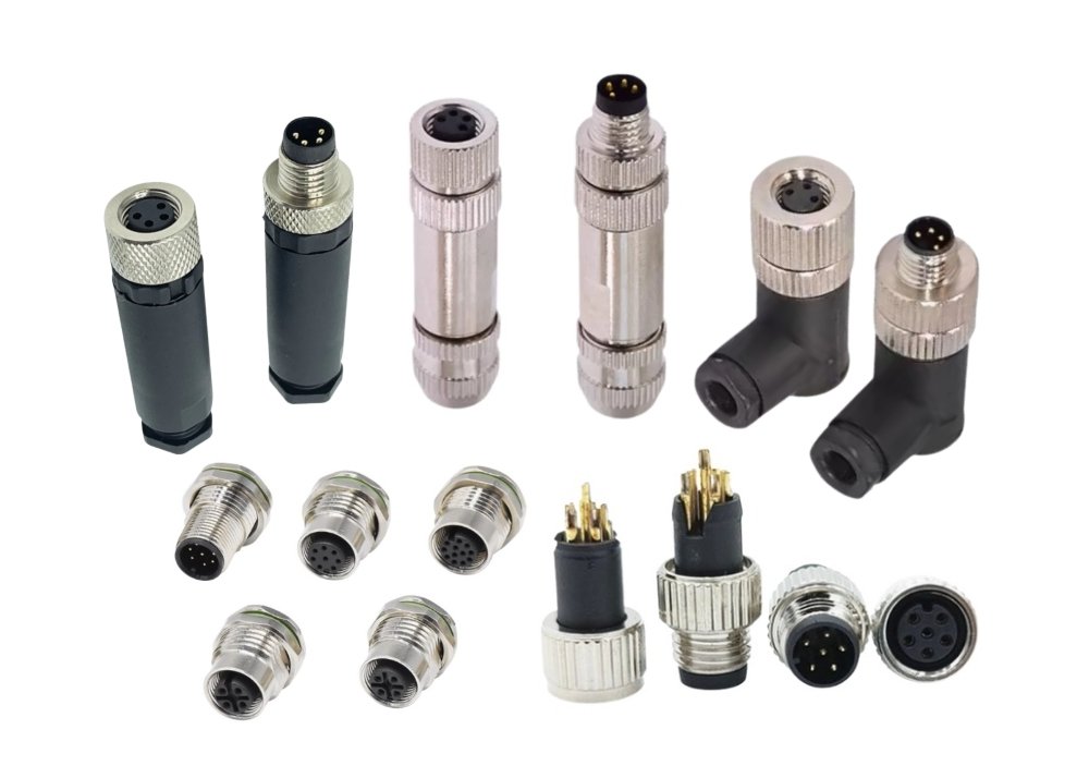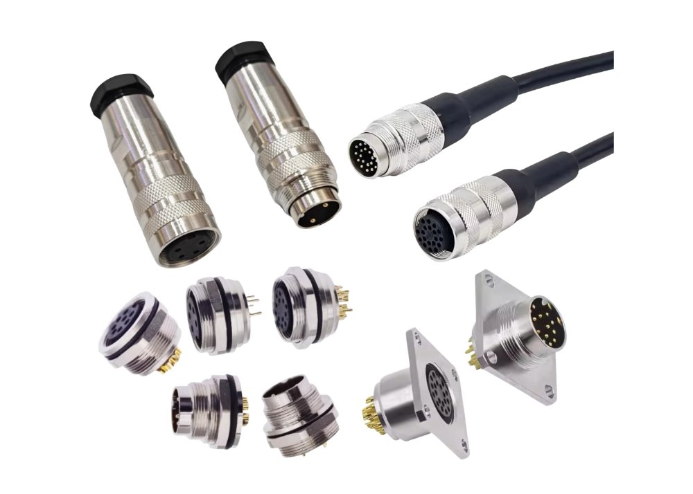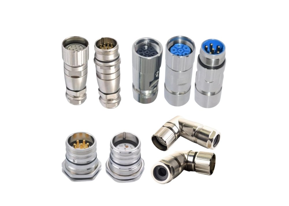

An RJ45 female connector forms the receptacle side of the 8P8C modular interface for twisted-pair Ethernet. This jack provides the physical and electrical bridge between a male plug and the network cabling or PCB electronics. Professionals distinguish the 8P8C name from the RJ45 label, a registration term often applied loosely across ethernet connectors. A connector factory may also supply related parts, such as an M8 connector or a Type B connector, for specialized networking links. Pinout, shielding, mounting, and magnetics define the core performance factors that network designers evaluate.
What Is an RJ45 Female Connector?
Definition and Primary Role
Receptacle Function in a Network Link
An RJ45 female connector is the receptacle half of the 8P8C modular interface. It accepts a male plug and carries signals between that plug and the cabling or circuit board behind it. The jack holds eight spring contacts. Each contact presses against a corresponding plug blade and completes one conductor path. This mechanical pressure creates a stable electrical junction for the life of the link.
Male Plug vs. Female Jack
The two halves of the interface serve different roles. The table below summarizes the split.
| Attribute | Male Plug | Female Jack |
|---|---|---|
| Position | Cable end | Panel or PCB |
| Contacts | Fixed blades | Spring-loaded |
| Motion | Inserts into jack | Receives plug |
| Retention | Latch tab | Latch window |
The male plug travels with the cable. The female jack stays fixed in a panel, faceplate, or device. A latch tab on the plug locks into a window on the jack. This pairing keeps the connection secure during vibration and cable movement.
RJ45 vs. 8P8C Naming
Standards and Registration Context
The RJ45 label comes from a telephone registration standard. That original standard defined a different keying arrangement. The networking industry later adopted the term for the eight-position modular interface. Strictly speaking, the correct name is 8P8C, which means eight positions and eight contacts.
Industry Usage Conventions
Professionals use both terms in daily work. Most catalogs list an ethernet connector under the RJ45 heading. Datasheets and standards documents favor 8P8C. A buyer who requests an RJ45 jack generally receives the eight-contact modular part. Clear communication matters when a project mixes voice and data hardware.
Where the Connector Sits in a Link
Patch Panel and Wall Outlet Positions
In structured cabling, the jack appears at two fixed points. A patch panel mounts the connector in a rack. A wall outlet or faceplate holds another jack near the user. Horizontal cable terminates on the rear of each jack. Patch cords then plug into the front.
Device-Side (PCB) Positions
Many devices solder the connector directly to a circuit board. Switches, routers, and embedded controllers use this arrangement. The PCB jack carries signals from the plug to the transceiver circuitry. Board-mounted parts often include magnetics or LEDs. This placement shortens signal paths and simplifies assembly.
Pinout and Internal Components of RJ45 Female Connectors
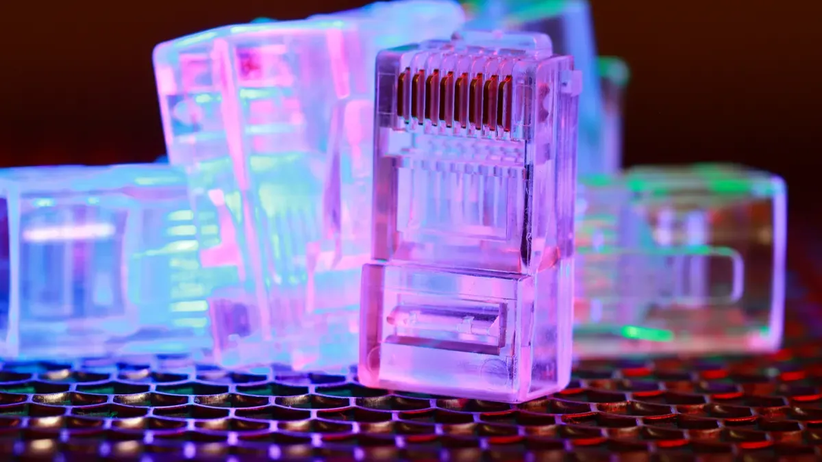
The Eight-Position Contact Layout
T568A and T568B Wiring Assignments
Two color-code schemes define conductor placement in the eight positions. The table below compares them.
| Pin | T568A | T568B |
|---|---|---|
| 1 | White/green | White/orange |
| 2 | Green | Orange |
| 3 | White/orange | White/green |
| 4 | Blue | Blue |
| 5 | White/blue | White/blue |
| 6 | Orange | Green |
| 7 | White/brown | White/brown |
| 8 | Brown | Brown |
Both schemes carry the same signal pairs. They differ only in the swap of the green and orange pairs. A network professional must apply one scheme consistently at both ends of every cable.
Pin Numbering Convention
Contacts number from left to right with the latch tab facing away from the viewer. This convention appears in pinout and wiring standards documents. Technicians count position one at the left edge of the jack opening. Consistent counting prevents miswired terminations during field assembly.
Internal Contact and Housing Components
Contact Blades and Plating
Each contact is a spring-tempered metal blade. Gold plating over nickel underplate resists corrosion and keeps contact resistance low. The plating thickness affects mating durability. Thin plating suits low-cost patch cords. Thicker plating serves high-cycle applications.
Housing, Latch, and Strain Relief Features
The thermoplastic housing holds the contacts in precise alignment. A latch window on the rj45 jack captures the plug tab. Strain relief features transfer cable pull forces away from the contact junctions. Robust housings survive repeated insertion cycles in dense panels.
Shielding and Grounding Elements
Shield Tabs and Ground Paths
Shielded connectors include metal shield tabs. These tabs contact the plug shield and route interference to ground. A short, low-impedance ground path protects signal integrity in noisy environments. Designers bond the shield to chassis ground at defined points.
Cable Shield Termination Points
The connector provides dedicated termination points for cable shields and drain wires. Proper termination of ethernet cables requires a 360-degree bond around the foil or braid. Poor shield termination creates an antenna effect. That effect couples noise into the signal pairs.
The rj45 female connector therefore combines precise contact geometry with shielding features that support reliable ethernet links. Careful attention to these internal details supports solid networking performance across the network.
Types and Classifications
Shielding Classifications
Unshielded (UTP) Connectors
Unshielded connectors serve standard twisted-pair runs in office and home environments. The plastic housing carries no metal shield. These parts cost less and install quickly. They suit installations where electromagnetic interference stays low. An unshielded rj45 jack works well with UTP cabling in typical commercial spaces.
Shielded (STP/FTP) Connectors
Shielded connectors add a metal shell around the housing. The shell bonds to the cable shield and drains interference to ground. These parts serve industrial sites, hospitals, and dense cabling trays. A shielded ethernet connector costs more and demands careful grounding. Installers must bond the shield at both ends for full effect.
| Attribute | UTP | STP/FTP |
|---|---|---|
| Shield | None | Metal shell |
| Cost | Lower | Higher |
| Grounding | Not required | Required |
| Best fit | Office LANs | Noisy environments |
Mounting Types
PCB Through-Hole and SMD Types
Board-mounted jacks come in two assembly styles. Through-hole parts use pins that pass through the board and solder on the back side. These parts resist mechanical stress well. SMD parts sit flat on the board surface and suit automated reflow lines. Designers choose the style that matches their assembly process and space budget.
Panel-Mount, Keystone, and Field-Termination Types
Panel-mount jacks bolt into a faceplate or chassis cutout. Keystone jacks snap into modular patch panels and wall outlets. Field-termination types accept bare wires on the rear and serve on-site cabling work. Each style fits a distinct position in the network. Technicians select the type that matches the installation point.
LED and Indicator Variants
Integrated Link/Activity LEDs
Many jacks include small LEDs that show link status and traffic activity. A steady light signals a live link. A blinking light shows data flow. Technicians read these indicators during troubleshooting. Integrated LEDs speed fault isolation in crowded racks.
LED Circuit Considerations
LED variants need extra wiring on the board or behind the panel. Each LED draws current and requires a series resistor. Designers must route the LED traces away from high-speed pairs. Poor routing couples noise into the signal path. Careful layout keeps the indicator function separate from data integrity.
Connectors with Integrated Magnetics
Integrated Magnetics Architecture
An rj45 with integrated magnetics combines the connector body with signal transformers and common-mode chokes inside one package. The magnetics sit between the plug contacts and the PCB pins. They provide isolation, impedance matching, and noise rejection for the ethernet link. This architecture removes the need for discrete transformer components on the board. An rj45 with integrated magnetics also shortens the signal path and improves repeatable performance across units.
Space and Design Tradeoffs
Board space is the main tradeoff. An rj45 with integrated magnetics occupies more footprint than a plain jack. The taller body can conflict with low-clearance enclosures. Thermal behavior also changes, because the magnetics generate slight heat under load. Designers gain simpler assembly and fewer solder joints in return. They must verify clearance, airflow, and pin compatibility before committing the layout.
Special and Ruggedized Types
Industrial and Sealed Variants
Industrial environments demand extra protection. Sealed variants add gaskets, threaded coupling, or IP-rated housings. These parts resist dust, moisture, and vibration on factory floors and outdoor cabinets. Metal shells provide shielding against motor drives and welding equipment. A rugged rj45 keeps the networking link stable where standard parts would fail. Installers must follow the sealing procedure carefully to preserve the rating.
Low-Profile and High-Density Variants
Dense racks and thin devices need compact parts. Low-profile jacks reduce height above the board and fit slim chassis. High-density variants stack ports in tight arrays for switches and patch panels. These designs save space but demand precise PCB layout and careful cable management. Technicians should confirm access clearance for the latch tab during service. A crowded network panel leaves little room for error.
Electrical and Mechanical Specifications
Electrical Characteristics
Contact Resistance and Current Rating
Contact resistance measures the opposition to current flow at the mated contact interface. A well-made rj45 female connector keeps this value low, typically under 20 milliohms. Low resistance preserves signal strength and reduces heat buildup. Current rating defines the maximum safe current per contact. Most rj45 parts carry 1.5 amps per contact. Power-over-Ethernet applications demand attention to this rating.
Voltage Rating and Insulation Resistance
Voltage rating specifies the maximum potential difference the connector withstands safely. Typical rj45 jacks rate at 150 volts AC. Insulation resistance measures the dielectric quality between contacts. High insulation resistance prevents leakage and crosstalk. A value above 500 megohms at 100 volts DC indicates sound insulation. Moisture and contamination degrade this property over time.
Insertion Loss and Return Loss Considerations
Insertion loss describes signal power lost as it passes through the connector. Return loss measures reflected signal energy at impedance mismatches. Both parameters grow critical at higher frequencies. Cat6A links require tight control of these losses. Connector geometry and plating quality directly affect both values. Designers should review datasheet curves across the full operating frequency band.
Mechanical Characteristics
Mating Cycles and Durability
Mating cycles define how many insertions a connector survives before performance degrades. Standard rj45 parts rate for 750 to 1,000 cycles. Gold plating thickness drives this number. Thicker plating extends service life in high-traffic ports. Network professionals should match cycle ratings to expected use patterns.
Insertion and Retention Force
Insertion force measures the push needed to seat a plug. Retention force measures the pull needed to remove it. Both values fall within defined ranges for reliable operation. Excessive insertion force damages contacts. Weak retention allows accidental disconnection. Standards specify acceptable limits for each parameter.
Operating Temperature Range
Temperature range defines the safe operating window. Commercial rj45 parts typically rate from -40°C to 85°C. Industrial variants extend this range further. Thermal cycling stresses solder joints and housing materials. Designers must verify the connector rating against the deployment environment.
Performance Categories and Compatibility
Category Ratings (Cat5e through Cat6A and Beyond)
Category ratings tie connector performance to ethernet cable capability. The table below summarizes common ratings.
| Category | Frequency | Typical Use |
|---|---|---|
| Cat5e | 100 MHz | Gigabit Ethernet |
| Cat6 | 250 MHz | 10G short runs |
| Cat6A | 500 MHz | 10G full runs |
A connector must match or exceed the cable category. Mixing lower-rated jacks with higher-rated ethernet cables wastes cable capability. The pinout and wiring standards remain consistent across categories.
Backward and Forward Compatibility Notes
Backward compatibility allows newer connectors to accept older plugs. An 8P8C interface maintains this compatibility across generations. Forward compatibility requires margin in the design. A Cat6A jack supports Cat5e links without issue. The reverse pairing limits performance to the lower category. Professionals should plan for future upgrades during initial networking builds. Proper category matching protects the network from bottlenecks.
PCB Mounting and Installation Guidelines

PCB Layout and Footprint Design
Land Pattern and Hole Placement
A correct land pattern forms the foundation of every reliable board-mounted jack. The datasheet supplies the exact pad dimensions, hole diameters, and spacing for each rj45 part. Designers should copy these values directly into the CAD library. Small deviations in hole placement cause misalignment during assembly. Misaligned pins stress the solder joints and weaken the mechanical bond.
Through-hole jacks need plated holes sized to the pin diameter. A clearance of roughly 0.1 mm around each pin allows smooth insertion. Oversized holes produce weak solder fillets. Undersized holes prevent full pin seating. The board outline must also clear the connector body and latch window. A tight outline blocks the plug tab and prevents full mating.
Mechanical support matters as much as electrical connection. Many rj45 jacks include locating pegs or mounting posts. These features anchor the body to the board and absorb insertion forces. The footprint must include matching holes for every post. Designers who omit these holes rely on solder joints alone. That choice shortens connector life in high-traffic ports.
Trace Routing and Impedance Control
Differential pairs demand controlled impedance from the connector pins to the transceiver. The target impedance is typically 100 ohms for standard ethernet links. Trace width, dielectric thickness, and spacing set this value. Designers should calculate the stackup before routing begins. A mismatch at the connector launch creates reflections that degrade return loss.
Pair routing follows a few firm rules. Traces within a pair run parallel and close together. Pair-to-pair spacing stays wide enough to limit crosstalk. Length matching within each pair keeps skew low. The four pairs should also match in total length across the board. These practices preserve signal quality at Cat6 and Cat6A frequencies.
Routing near the connector deserves special care. Vias and layer changes should sit away from the signal pins. Power and ground planes provide return paths beneath the traces. A solid reference plane under the signal layer controls impedance and shields the pairs. Designers should avoid splits or voids in that plane. Any discontinuity forces return current to detour and radiates noise.
Soldering and Assembly Practices
Through-Hole Soldering Guidelines
Through-hole assembly follows a defined sequence. The basic installation steps below apply to most board-mounted jacks.
- Insert the connector pins into the plated holes until the body seats flat.
- Verify that all pins pass through and the body sits square to the board.
- Apply flux to the joint area according to the process specification.
- Solder the mounting posts first to lock the body position.
- Solder the signal pins with a controlled iron or wave process.
- Inspect each fillet for full wetting and a smooth concave shape.
Iron temperature typically ranges from 350°C to 380°C for lead-free solder. Contact time per pin should stay under three seconds. Excessive heat damages the thermoplastic housing and lifts pads. A wave solder process suits high-volume runs. The wave height and dwell time must cover every joint without flooding the housing.
Cleanliness affects long-term reliability. Flux residue traps moisture and promotes corrosion. The assembly team should clean boards per the flux manufacturer’s guidance. Aqueous cleaning works well for most no-clean and water-soluble fluxes. Drying must be complete before the connector sees power.
SMD Reflow Considerations
SMD jacks require a reflow profile matched to the part and the paste. The profile has four zones: preheat, soak, reflow, and cooling. Ramp rates should stay gentle to prevent thermal shock. Peak temperature must not exceed the connector’s rated limit. Most SMD rj45 parts tolerate peaks near 260°C for short durations.
The paste deposit controls joint quality. Stencil thickness and aperture design set the paste volume. Too little paste leaves open joints. Too much paste causes bridging between fine-pitch pins. The placement machine must seat the part flat with minimal offset. A tilted part produces uneven joints and weak retention.
Moisture sensitivity deserves attention for parts with integrated magnetics. These packages can absorb moisture during storage. A bake-out before reflow prevents popcorning and internal cracks. The datasheet states the moisture sensitivity level and the required bake conditions. Assembly teams should log bake cycles and storage exposure.
Cable Termination Best Practices
Wire Untwisting and Trim Lengths
Cable termination quality depends on how the installer handles the pairs. Each pair stays twisted until the point of termination. Untwisting should cover no more than 13 mm for Cat6 and Cat6A work. Longer untwisted sections raise crosstalk and degrade near-end performance. The installer should keep the pair lay intact right up to the wire guide.
Trim lengths follow the connector or jack specification. Excess conductor length creates stray capacitance and crosstalk. Short conductors may not reach the contact slots. A flush cut at the specified gauge gives consistent results. The installer should use a dedicated termination tool for repeatable cuts.
Wire management inside the connector body affects strain relief. The cable jacket should enter the connector and clamp under the strain relief bar. This clamp transfers pull forces away from the contacts. A jacket that stops short of the clamp leaves the conductors carrying the load. That arrangement fails under normal cable handling.
Shield and Drain Wire Termination
Shielded cabling needs a full 360-degree bond at the connector. The foil or braid folds back over the jacket and contacts the metal shell. A clamp or crimp ring secures the bond around the full circumference. Partial contact creates an antenna effect and couples noise into the pairs. The installer should verify the bond with a visual check and a pull test.
Drain wires require a short, direct path to the shield or ground point. A long drain wire pigtail adds inductance and reduces shield effectiveness. The installer should trim the drain wire to the shortest practical length. Secure termination of the drain wire at the designated ground tab completes the path.
Proper installation of shielded links also depends on grounding at both ends. The shield carries no signal current, so a single-point ground leaves the far end floating. That floating section acts as a receiving antenna. Bonding both ends equalizes potential and drains interference. The network then sees a stable, low-impedance ground path along the full run.
Consistent workmanship across every port protects the whole network. A single poorly terminated link can degrade performance for adjacent channels. The installation tips above apply to patch panels, wall outlets, and field connectors alike. Teams should document their termination standard and inspect samples from each batch. This discipline turns a pcb mounting guide into a repeatable process.
Inspection and Testing
Inspection and testing close the loop on every termination job. A technician who skips these steps leaves link quality to chance. Systematic checks catch defects before they reach the production network. The two stages work together: visual inspection finds physical faults, and electrical testing confirms performance.
Visual Inspection Criteria
Visual inspection happens first and costs almost nothing. The technician examines each rj45 termination under good light, often with a magnifier. Several defects appear at this stage without any test equipment.
| Check Point | Acceptable Condition | Common Defect |
|---|---|---|
| Contact seating | All eight blades level and fully inserted | Recessed or bent blade |
| Wire order | Matches T568A or T568B at both ends | Swapped pair |
| Jacket entry | Jacket reaches the strain relief clamp | Jacket stripped too short |
| Untwisted length | Under 13 mm at the termination point | Long untwisted section |
| Shield bond | Full 360-degree contact with the shell | Partial or loose contact |
| Housing | No cracks, latch window clear | Cracked body or blocked latch |
The technician should confirm that every conductor reaches its contact slot. A wire that stops short of the slot creates an open circuit. A wire that crosses into a neighboring slot creates a short or a split pair. Both faults degrade the ethernet link and often escape casual checks.
Housing condition deserves equal attention. Cracks in the thermoplastic body weaken contact alignment over time. A blocked latch window prevents the plug from locking. The technician should also verify that the latch tab on a test plug engages and releases smoothly. Stiff or loose engagement signals a damaged jack.
Shielded terminations need a dedicated visual check. The installer folds the foil or braid back over the jacket and clamps it under the metal shell. The technician inspects the full circumference for gaps. A partial bond defeats the shield and turns the cable into a noise antenna. A gentle pull on the cable confirms that the clamp holds.
Documentation supports consistent quality. The inspection team should record results for each batch and flag recurring defects. A pattern of split pairs points to a training gap. Repeated shield faults suggest a tooling problem. This feedback loop improves the installation process over time.
Continuity and Performance Testing
Electrical testing follows visual inspection. The technician connects each link to a cable tester and runs the appropriate test suite. Basic continuity tests confirm that all eight conductors reach both ends in the correct order. The tester reports opens, shorts, and miswires by pin number. A split pair shows up as a specific fault pattern that the technician can trace to the termination.
Performance testing goes beyond continuity. The cable tester measures insertion loss, return loss, and crosstalk across the rated frequency band. These measurements confirm that the link meets its category specification. A Cat6A link must pass at 500 MHz. A Cat5e link passes at 100 MHz. The tester compares results against the standard limits and issues a pass or fail verdict.
Length measurement rounds out the basic test set. Excessive length adds loss and delay. The tester reports the physical length of each pair. Skew between pairs also matters for high-speed links. Large skew values indicate a routing or termination problem.
Test results should be saved and archived. A stored report gives the networking team a baseline for future troubleshooting. When a link fails months later, the original data shows whether the fault is new. This record also supports warranty claims and compliance audits.
Failed links require a disciplined response. The technician should re-terminate the affected end and retest. Repeated failures may point to a damaged jack or a cable fault. The rj45 female connector itself rarely fails when the installation follows good practice. Most failures trace back to workmanship at the termination point.
Final acceptance depends on a complete test pass for every link. Partial passes leave hidden risk in the network. A single marginal link can cause intermittent errors that are hard to diagnose. Thorough testing at handover protects the network through its full service life.
Common Applications of RJ45 Female Connectors in Network Infrastructure
The applications of rj45 female connectors span nearly every layer of a modern data network. Each deployment site places different demands on the part. A rack-mounted patch panel values density and labeling. A wall outlet values durability and clean appearance. A factory-floor device values sealing and shielding. This section examines the major application areas and the connector requirements that each one drives.
Enterprise and Data Center Cabling
Enterprise and data center environments concentrate enormous numbers of ports into small spaces. A single rack may hold hundreds of links. Connector reliability and consistent performance matter more here than in any other setting. A failed port in a data center can interrupt services for thousands of users.
Patch Panels and Rack Systems
Patch panels form the cross-connect point of enterprise cabling. Each panel holds a row of rj45 female connectors on the front and termination points on the rear. Horizontal cable lands on the rear contacts. Patch cords plug into the front ports and route traffic to switches. Technicians use these panels to reconfigure links without touching the permanent cabling.
Rack systems demand high port density. A 1U panel typically holds 24 or 48 ports. High-density variants pack even more jacks into the same space. Designers must balance density against service access. A crowded panel leaves little room for fingers to release a latch tab. Technicians should confirm clearance before specifying a high-density part.
Labeling and cable management complete the patch panel picture. Clear port labels speed moves, adds, and changes. Horizontal and vertical managers route patch cords away from the connector faces. Proper management reduces strain on the rj45 jack and extends its service life. These practices keep the network organized through years of change.
Switch and Server Port Interfaces
Switches and servers carry the rj45 female connector directly on the circuit board. A 48-port switch mounts 48 jacks in a tight front-panel array. Each jack connects to a PHY chip through controlled-impedance traces. Many designs integrate magnetics inside the connector body to save board space. LEDs sit beside each port to show link and activity status.
Server ports follow a similar pattern. Motherboards and network interface cards mount one or more jacks on the rear panel. These ports often carry Power-over-Ethernet in voice and camera deployments. The connector must handle the added current without excess heating. Designers should verify the current rating per contact before specifying a part.
Data center switches push port counts higher with each generation. Thermal management becomes a design constraint at these densities. Integrated magnetics generate slight heat under load. Airflow paths must reach every connector body. Designers who ignore this detail risk hot spots and reduced component life.
Structured Building Cabling
Structured cabling brings the network to every desk, conference room, and office. The design follows a hierarchical plan. Horizontal cable runs from a telecommunications room to each work area. The connector appears at both ends of that run. Consistent installation practice across thousands of outlets protects the whole building network.
Wall Outlets and Faceplates
Wall outlets place an rj45 female connector where users can reach it. A keystone jack snaps into a faceplate and presents one or more ports at the wall. The installer terminates the horizontal cable on the rear of the jack. The user then plugs a patch cord into the front. This arrangement keeps the permanent cable protected inside the wall.
Faceplate design affects both function and appearance. Angled faceplates direct patch cords downward and reduce strain on the plug and jack. Shuttered outlets protect the contacts from dust when no cable is plugged in. Labeling on the faceplate identifies the port for troubleshooting. These small details improve the user experience and simplify maintenance.
Outlet placement follows cabling standards and building codes. Each work area typically receives at least two ports to allow for voice and data or future growth. The installer must leave service loops and respect bend radius limits behind the wall. A poorly installed outlet may pass testing at first and fail months later under cable stress.
Horizontal Cabling Terminations
Horizontal cabling describes the permanent link from the telecommunications room to the work area outlet. This run may span up to 90 meters under standard limits. The rj45 female connector terminates each end. Termination quality directly determines whether the link meets its category rating.
Installers face several challenges on horizontal runs. Cable pulls through conduit and ceiling spaces can stress the conductors. The installer must strip the jacket carefully and preserve pair twists to the termination point. Excess untwisting raises crosstalk and can fail a Cat6A certification test. A disciplined termination process prevents these faults.
Testing confirms that each horizontal link meets its specification. The technician runs insertion loss, return loss, and crosstalk tests across the rated band. Failed links require re-termination and retest. Documentation of every link gives the building owner a record for future moves and upgrades. This record supports the long-term value of the cabling infrastructure.
Industrial and Embedded Networking
Industrial and embedded settings push connectors beyond the office environment. Vibration, moisture, dust, and electrical noise all appear on the factory floor. Embedded devices add their own constraints of space and power. Connector selection must address these conditions from the start.
Industrial Ethernet Equipment
Industrial ethernet equipment operates where standard office parts would fail. Motor drives, welding systems, and heavy machinery generate strong electromagnetic fields. Shielded connectors with metal shells route interference to ground. Sealed variants add gaskets and IP-rated housings against dust and washdown. These parts keep the network link stable in harsh conditions.
Temperature range separates industrial parts from commercial ones. Factory floors and outdoor cabinets see temperature swings well beyond office norms. Industrial jacks extend the operating window and resist thermal cycling. The installer must follow the sealing procedure exactly to preserve the rating. A loose gasket or a missing coupling ring defeats the protection.
Vibration resistance also matters on the plant floor. Threaded coupling or locking mechanisms hold the plug in place where a standard latch might release. These designs suit moving equipment and machine-mounted ports. The network then survives the mechanical stress that comes with production work.
Embedded Device Connectivity
Embedded devices bring ethernet networking to controllers, sensors, and small-form-factor equipment. A single-board computer may mount one rj45 jack on its edge. A camera or access point may hide the port inside a sealed enclosure. These designs value small footprints and low power draw.
Board space drives many embedded decisions. Low-profile jacks reduce height above the board and fit slim chassis. SMD variants suit automated assembly lines and high-volume production. Integrated magnetics remove discrete transformer components and simplify the layout. Each choice trades space against cost and assembly complexity.
Embedded designs also face signal integrity challenges. Short traces between the jack and the PHY chip help, but layout discipline still matters. Controlled impedance, solid reference planes, and careful pair routing protect the link. Designers should review the connector datasheet and follow the recommended footprint. These steps prevent costly redesigns after the first prototype build.
The table below summarizes how the three application areas compare on key connector priorities.
| Priority | Enterprise/Data Center | Structured Cabling | Industrial/Embedded |
|---|---|---|---|
| Port density | Very high | Moderate | Low to moderate |
| Shielding need | Moderate | Low to moderate | High |
| Environmental sealing | Low | Low | High |
| Space constraint | High | Low | Very high |
| Service access | Critical | Moderate | Limited |
Each application area draws on the same core connector technology. The differences lie in the priorities and the environment. A network professional who understands these differences can match the part to the job. That match protects performance and extends service life across the full network.
Proper Installation and Selection of the Right Connector
Technical Performance Fit
Category and Shielding Match to Cabling
The connector must match the cable category and shielding type. A Cat6A rj45 jack paired with Cat5e ethernet cables wastes the cable’s capability. Shielded connectors belong with shielded cabling. Mixing shielded jacks with unshielded cable leaves the shield unterminated. That mismatch creates a noise path into the link. Professionals should confirm the category rating and shield type on both the jack and the cable datasheet before purchase.
Electrical and Mechanical Requirement Checks
Designers verify current rating, voltage rating, and contact resistance against the application. Power-over-Ethernet loads demand attention to per-contact current limits. Mating cycle ratings should match expected port traffic. High-use ports need thicker gold plating. The rj45 female connector datasheet lists these values, and the design team should check each one against the deployment plan.
Application and Environment Fit
Mounting Style and Space Constraints
Mounting style follows the installation point. Patch panels and wall outlets take keystone or panel-mount parts. Switches and embedded devices take PCB through-hole or SMD jacks. Low-profile variants fit slim chassis. High-density arrays suit crowded racks. Designers should confirm latch access clearance during service. A tight layout blocks the plug tab and frustrates technicians.
Environmental and Durability Needs
The environment sets the durability requirement. Office spaces accept standard commercial parts. Factory floors need sealed, shielded variants with extended temperature ranges. Outdoor cabinets demand IP-rated housings. Vibration-prone equipment benefits from threaded coupling. Matching the part to the environment prevents premature failure and protects the networking link over its service life.
Compliance and Standards
Relevant Standards and Certifications
Connectors should carry certification to recognized standards. The table below lists the common references.
| Standard | Scope |
|---|---|
| TIA-568 | Commercial cabling |
| ISO/IEC 11801 | Generic cabling |
| IEC 60603-7 | 8-way connector detail |
| UL 1863 | Communications circuit accessories |
Certification confirms that the part meets defined performance and safety criteria. Buyers should request test reports from the supplier.
Flammability and Safety Ratings
Housing materials carry flammability ratings such as UL 94 V-0. Plenum spaces demand specific ratings under building codes. The wiring in air-handling spaces must limit smoke and flame spread. Designers should confirm the rating against local code requirements. Proper installation depends on these ratings, and a noncompliant part can fail inspection.
Selection discipline protects the network from avoidable faults. Each check above takes minutes and prevents costly rework later.
Cost and Lifecycle Considerations
Unit Cost vs. Total Installed Cost
A low unit price rarely tells the full cost story. The purchase price of an rj45 female connector covers only the part itself. Installation labor, testing time, and rework expenses add to the real cost of every port. A cheap jack that fails inspection forces a technician to re-terminate the link and retest it. That rework often costs more than the price difference between a budget part and a quality part.
The table below compares the cost factors that matter across a connector’s service life.
| Cost Factor | Budget Part | Quality Part |
|---|---|---|
| Unit price | Lower | Higher |
| Termination time | Longer | Shorter |
| Rework rate | Higher | Lower |
| Service life | Shorter | Longer |
Professionals should weigh these factors together. A slightly higher unit price often delivers a lower total installed cost. Durable plating and precise contact geometry reduce failures during certification. Fewer failures mean less labor and less downtime. Buyers who focus only on the invoice price may pay more over the full lifecycle.
Availability and Long-Term Supply Planning
Supply continuity protects a network project from delays. A connector that goes out of stock can halt an installation mid-run. Designers should confirm that the chosen rj45 part has stable distribution and multiple sources. Long production runs benefit from a supplier with consistent lead times. Short-term savings from a discontinued part rarely justify the redesign cost later.
Lifecycle planning also covers revision changes. Manufacturers sometimes update housings, plating, or pin layouts. A revision can affect the PCB footprint or the mating fit. The design team should track part numbers and review change notices. Locking a bill of materials to a qualified part number prevents surprises during production.
Spare inventory rounds out the plan. A small stock of rj45 jacks supports field repairs and future expansions. Technicians can replace a damaged port without waiting for a new order. This buffer keeps the network running through minor failures. Combined with stable sourcing, spare stock protects the investment in the cabling infrastructure.
The rj45 female connector serves as the physical foundation of every twisted-pair ethernet link. Pinout accuracy, shielding consistency, and correct termination determine link performance. Professionals can use the classification framework—shielding, mounting, LED, magnetics, and special types—as a selection checklist. Connector specifications must match cable category, environment, and compliance requirements. The rj45 female connectors in any network infrastructure demand careful selection. Disciplined installation protects networking reliability across the full lifecycle. Proper rj45 choices strengthen the entire infrastructure and keep the network stable for years.
FAQ
What distinguishes an RJ45 female connector from an 8P8C jack?
The two names describe the same eight-position, eight-contact interface. The RJ45 label comes from a telephone registration standard. The networking industry adopted the term for data jacks. Professionals treat 8P8C as the precise technical name and RJ45 as the common catalog term.
Which wiring scheme should a technician apply, T568A or T568B?
Both schemes carry identical signal pairs and deliver the same performance. The technician must apply one scheme consistently at both ends of every cable. Most commercial installations in the United States use T568B. Mixed schemes at opposite ends create a crossover and break the link.
When does a shielded connector justify its higher cost?
A shielded connector fits environments with strong electromagnetic interference. Industrial sites, hospitals, and dense cable trays qualify. The installer must bond the shield at both ends for full effect. Office LANs with low interference work well with unshielded parts.
Can a Cat6A jack support a Cat5e link?
Yes. The higher-rated jack accepts the lower-category plug and passes the signal without issue. The reverse pairing limits performance to the lower category. Designers should specify jacks at or above the cable category to preserve future upgrade headroom.
What advantage do rj45 female connectors with integrated magnetics offer?
Integrated magnetics combine transformers and chokes inside the connector body. This architecture removes discrete components from the board and shortens the signal path. Assembly simplifies, and unit-to-unit performance becomes more repeatable. The tradeoff is a larger footprint and slight heat under load.
How many mating cycles should a network professional expect?
Standard jacks rate for 750 to 1,000 insertion cycles. Gold plating thickness drives this number. High-traffic ports benefit from thicker plating and higher cycle ratings. Technicians should match the rating to expected use patterns before specifying a part.
What causes a link to fail certification after a seemingly correct termination?
Excess untwisting ranks as the most common cause. Installers should keep pair twists intact to within 13 mm of the contact slots. Split pairs, short jacket entry, and partial shield bonds also fail tests. Visual inspection catches most of these faults before testing begins.
Does a low unit price indicate a good connector value?
Unit price covers only the part itself. Installation labor, rework, and downtime add to the real cost of every port. A quality jack with durable plating reduces failures during certification. Buyers should weigh total installed cost against the invoice price.