In modern electronic equipment and electrical systems, connectors are key components, and their performance directly affects the reliability and stability of the entire system. Whether in the fields of aerospace, national defense, industrial machinery or consumer electronics, the selection of connectors is a technical decision that requires comprehensive consideration of multiple factors. This article will start with the basic classification of connectors, and analyze in detail the core consideration dimensions such as electrical performance parameters, mechanical characteristics, environmental adaptability, and material processes. It will also introduce professional testing and verification methods, and finally provide connector selection recommendations for different application scenarios. Through systematic selection ideas and practical guidelines, it helps engineers and technicians avoid common pitfalls, select connector solutions that truly meet project needs, and ensure that the equipment can maintain stable and reliable connection performance under various harsh conditions.
The basis of connector selection: classification and core considerations
As an indispensable electromechanical component in electronic equipment, connectors come in a wide variety of types and specifications, from simple board-to-board connections to complex multi-pin aviation plugs, showing great diversity. Faced with thousands of connector types on the market, engineers must first clarify the basic selection principles in order to quickly narrow down the range of options and find the connector product that best suits a specific application. The selection of connectors is not a simple parameter comparison, but a technical decision that requires a comprehensive evaluation of electrical requirements, mechanical constraints, and environmental conditions.
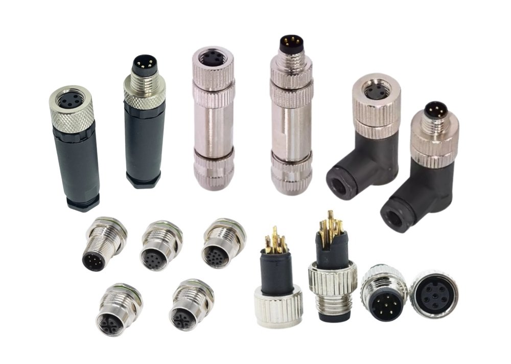
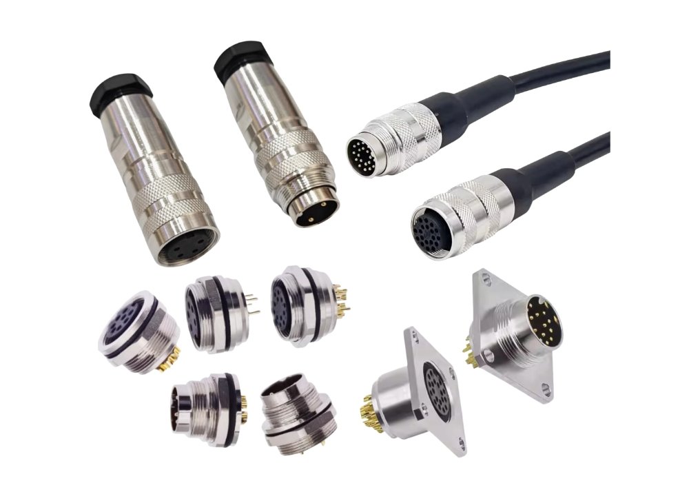
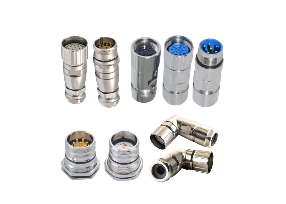
According to the connector level classification, the National Electrical Distributors Association (NEDA) divides it into five categories: wire-to-board or wire-to-wire connectors, box-to-box or input/output level connectors, IC chip or chip-to-package level connectors, IC package or board-level package connectors, and PCB board-to-board connectors. This classification method covers all connection scenarios from the micro chip level to the macro device level, providing a systematic framework for selection. In actual applications, the more common classification method is to distinguish according to the appearance structure , mainly including circular connectors (such as aviation plugs), rectangular connectors, strip connectors, and special-shaped connectors. Circular connectors dominate the aerospace and military fields due to their excellent vibration resistance and easy wiring; rectangular connectors are widely used in industrial control and data transmission scenarios due to their high-density layout advantages.
From the perspective of frequency characteristics , connectors can be divided into two categories: high frequency and low frequency. High-frequency connectors (such as RF coaxial connectors) need to pay special attention to impedance matching and signal integrity, and usually use low-loss dielectric materials such as PTFE; while low-frequency connectors mainly meet basic conductive needs, and are relatively more focused on current carrying capacity and contact resistance. In addition, according to the purpose , they can be divided into power connectors, signal connectors, data connectors, and special-purpose connectors, etc. Each category has its own unique design focus and performance indicators. For example, power connectors emphasize high current transmission and low contact resistance, while data connectors pay more attention to transmission rate and shielding performance.
Application scenario is the primary consideration in connector selection. The requirements for connectors in different application fields vary significantly: consumer electronics products pursue miniaturization and low cost, industrial equipment focuses on reliability and environmental tolerance, while aerospace and military applications place extreme demands on connectors’ vibration resistance, temperature adaptability and life. For example, in mobile phone manufacturing, commonly used connector types include FPC flexible circuit connectors, board-to-board connectors, and external interface connectors such as USB and SIM cards; while in communication base station equipment, RJ45 network interfaces, fiber optic connectors, and high-frequency coaxial connectors are more commonly used. Clarifying application scenarios and requirements is the first step in connector selection and is also the basis for all subsequent technical decisions.
In the connector selection process, brand and supply chain factors should not be ignored. Internationally renowned brands such as TE Connectivity, Amphenol, and Molex have taken a leading position in the high-end connector market with their long-term technology accumulation and strict quality control. Their products usually have more reliable performance and more complete technical documentation support. However, brand premiums may also bring cost pressures, so a careful balance needs to be made between quality and budget. For price-sensitive applications such as consumer electronics, connector products provided by domestic manufacturers may have more cost-effective advantages. Regardless of the brand chosen, the supplier’s technical support capabilities, delivery stability, and after-sales service level should be included in the evaluation scope to ensure the smooth progress of the entire project cycle.
Electrical performance parameters: key choices to ensure stable and safe connections
The most essential function of the connector is to establish a reliable channel for electrical signal and power transmission, so electrical performance parameters are hard indicators that need to be determined first during the selection process. These parameters not only directly affect the realization of the basic functions of the connector, but also the safety and stability of the entire electrical system. Rated voltage and rated current are the most basic and critical electrical parameters in connector selection, which determine whether the connector can meet the basic working requirements of the circuit. The rated voltage mainly depends on the insulating material used in the connector and the spacing between the contact pairs, while the rated current is closely related to the material and cross-sectional area of the contact. Engineers must ensure that the rated value of the selected connector is higher than the maximum expected value in the actual application and retain sufficient safety margin. Especially in high-voltage applications, the insulation performance of the connector is more critical, and it is usually necessary to select materials with strong insulation properties such as PTFE or ceramics.
Current carrying capacity is directly related to the thermal design of the connector. When current passes through the contact pair, Joule heating effect will occur due to the presence of conductor resistance and contact resistance, causing the temperature to rise. Excessive temperature rise may damage the insulating material or accelerate the oxidation of the surface plating of the contact, thereby causing failure. It is worth noting that for multi-core connectors, the rated current usually needs to be derated – the more cores there are, the greater the derating. For example, the rated current of a certain specification of contact pair is 50A in the case of a single core, but it may need to be derated to 38A per core in a 5-core application. This phenomenon is particularly prominent in high-current applications. This derating requirement is due to the difficulty in heat dissipation caused by the concentrated heat of multi-core connectors. Engineers must give full consideration when selecting to avoid the risk of overheating.
Contact resistance is the core parameter to measure the conductive efficiency of the connector. It consists of two parts: the conductor resistance of the contact itself and the contact interface resistance. Stable, low contact resistance is critical to ensuring signal integrity and reducing power loss, especially in small signal and precision measurement circuits where even milliohm resistance differences can cause significant measurement errors. The size of the contact resistance mainly depends on factors such as the material of the contact, the quality of the coating and the contact pressure. Although gold plating is more expensive, it excels in oxidation resistance and contact resistance stability, making it very suitable for small signal and frequent plugging and unplugging applications; while silver plating is more cost-effective in high current applications. It should be noted that the contact resistance values provided by connector samples are usually measured under ideal conditions. In actual applications, due to factors such as oxidation, contamination or mechanical looseness, the contact resistance may gradually increase. Therefore, sufficient design margin should be reserved when selecting.
For high-frequency and high-speed digital signal applications, impedance matching and signal integrity become key considerations in connector selection. Impedance mismatch can cause signal reflection, waveform distortion and reduced transmission quality. RF coaxial connectors are usually designed with a characteristic impedance of 50Ω or 75Ω, which must be consistent with the transmission line impedance to ensure signal transmission quality. In the field of high-speed data communications (such as 5G, USB 3.0, HDMI, etc.), the connector’s crosstalk suppression capability and transmission delay cannot be ignored. Capacitive coupling and inductive coupling between adjacent signal lines of multi-pin connectors may cause crosstalk problems, especially in backplane connectors with high-density layout. To meet this challenge, high-end connector products usually adopt designs such as staggered ground line layout, differential pair structure or integrated shielding layer to ensure the transmission quality of high-speed signals.
Insulation performance parameters include insulation resistance and withstand voltage, which are directly related to the safety and reliability of the connector. Insulation resistance refers to the resistance value presented when voltage is applied to the insulating part of the connector, which is mainly affected by the characteristics of the insulation material, temperature, humidity and surface contamination. The withstand voltage refers to the maximum voltage that can be tolerated between contact pairs or between a contact pair and the casing without breakdown. This parameter is particularly important in high voltage applications. In actual selection, special attention should be paid to the difference between test conditions and usage environment – the insulation parameters provided by connector samples are usually measured under standard atmospheric conditions, while in high temperature, high humidity or polluted environments, these performances may be significantly reduced. For connectors working in special environments (such as high altitude and low pressure conditions), the impact of air pressure changes on insulation performance must also be considered. If necessary, derating should be performed or air-sealed products should be selected.
the shielding effectiveness of connectors has also become an important evaluation indicator when selecting. A good shielding design can prevent the intrusion of external electromagnetic interference while suppressing internal signal radiation. Metal shell connectors combined with shielded cables can form a complete electromagnetic shielding system, which is essential for EMI-sensitive applications such as medical equipment and communication base stations. When selecting a shielded connector, special attention should be paid to the conductivity of the shell material, the contact quality of the shell joint, and the termination method of the cable shield to ensure the integrity of the entire shielding system. Some high-end connector products also use a composite shielding design, such as a metal shell combined with an internal insulation coating, which can simultaneously cope with high-frequency and low-frequency interference, providing comprehensive protection for sensitive circuits.

Mechanical properties and environmental adaptability: ensuring the reliability of connectors under harsh conditions
Connectors not only need to meet electrical performance requirements, but also must have sufficient mechanical strength and durability to withstand various physical stresses and environmental challenges in actual applications. Mechanical performance is the basic guarantee for the long-term and reliable operation of connectors, especially in harsh applications such as aerospace, military equipment and industrial equipment. Structural dimensions are the first mechanical parameters to be considered in connector selection. It is necessary to ensure that the connector’s overall dimensions and installation method match the space limitations of the equipment. In electronic devices with dense PCB layouts, the risk of interference between connectors and other components requires special attention; in portable devices, the weight and volume of connectors may also become important considerations. As the trend of miniaturization of electronic devices continues, the demand for high-density micro connectors (such as M.2, Micro-D, etc.) is growing. These connectors enable the integration of more signal channels in a limited space, but at the same time they also place higher requirements on plug-in accuracy and mechanical strength.
The plug-in life is a core indicator to measure the durability of the connector, usually expressed in terms of the rated number of plug-in cycles. The plugging and unplugging life of commercial-grade connectors is generally in the range of 500-1000 times, while industrial-grade and high-reliability connectors can reach tens of thousands of times or more. It is worth noting that the plugging life is closely related to the conditions of use – in the case of plugging and unplugging under load or in the presence of mechanical stress, the actual life may be significantly reduced. For applications that require frequent plugging and unplugging (such as test equipment interfaces, replaceable modules, etc.), specially designed high-durability connectors should be selected. Such products usually use gold-plated contacts, reinforced spring structures or low-friction insulation materials to extend service life. On the contrary, in the case of permanent or semi-permanent connections, connection stability and cost factors can be prioritized without excessively pursuing a high number of plug-in and unplug cycles.
Contact pressure is a key mechanical parameter that affects connector performance, which directly determines the stability and conductivity of the contact interface. Sufficient contact pressure can destroy the oxide film on the contact surface and establish direct contact between metals, thereby reducing contact resistance and improving stability. In circular pin-socket connectors, contact pressure is usually indirectly evaluated by single-pin separation force, which measures the force required to pull the pin out of the socket. The total separation force (the sum of the separation forces of all contact pairs) reflects the difficulty of plugging and unplugging the entire connector. When the total separation force exceeds 50N, manual plugging and unplugging may be quite laborious. For applications that require frequent plugging and unplugging or are space-constrained, zero insertion force (ZIF) or low insertion force connectors can be selected. These products use special mechanical structure designs to reduce resistance during plugging and unplugging and establish stable contact after locking.
Vibration and shock resistance are critical for connectors used on mobile platforms or in harsh industrial environments. Mechanical vibration and shock may cause micro-movement of the contact interface, resulting in fluctuations in contact resistance or even momentary circuit breakage, which may cause signal interruption or arc damage in severe cases. In aviation, aerospace and military applications, connectors are usually required to withstand random vibration tests with a frequency range of 10-2000Hz and an acceleration of 10-50g. To improve vibration resistance, products with threaded locking, bayonet locking or secondary locking mechanisms can be selected. These designs can effectively prevent the connector from loosening in a vibrating environment. For example, the MIL-DTL-38999 series of high-reliability aviation connectors use a three-head threaded connection method combined with an elastic contact design to meet the most stringent military and aerospace application requirements.
connection method should be based on comprehensive considerations of installation space, operating frequency and environmental conditions. Common connection methods include threaded connection, bayonet connection, pin connection and direct plug-in self-locking. Threaded connection provides the most secure mechanical fixation, but the plug-in and pull-out speed is slow; bayonet connection (such as BNC connector) achieves a balance between fast plug-in and pull-out and reliable fixation; and pin-type connection is the fastest of the three methods, and only linear motion is required to complete the connection and locking, which is particularly suitable for occasions where space is limited and quick disassembly and assembly are required. In the field of industrial automation, the M12 and M8 series micro connectors have become standard interfaces for sensors and fieldbus devices due to their compact threaded connection design; in medical equipment, snap-on connectors with color coding and anti-misinsertion design are more popular, facilitating quick operation and reducing the risk of human error.
Environmental adaptability is an important aspect that cannot be ignored in connector selection. Products with corresponding protection levels and material properties must be selected according to the actual application environment. Temperature extremes are a common challenge faced by many industrial applications – high temperatures may soften and lose elasticity of insulating materials, while low temperatures may cause brittle cracking of materials. The operating temperature range of commercial connectors is usually between -25°C and +85°C, industrial-grade products can reach -40°C to +105°C, and aerospace-specific connectors may be required to withstand extreme temperatures of -65°C to +200°C. In high-temperature environments, insulating materials with excellent heat resistance such as LCP (liquid crystal polymer) or PPS should be selected; in low-temperature applications, attention should be paid to the flexibility and impact resistance of the material at low temperatures.
The protection level system (IP code) provides a standardized description of the connector’s ability to resist dust and water, which is particularly important for applications in outdoor, humid or dusty environments. The IP67 rating indicates that the connector is completely dustproof and can withstand temporary immersion, while the IP69K rating indicates that the product can withstand high-pressure and high-temperature water washing, which is suitable for harsh environments such as food processing and chemical equipment. In corrosive environments such as marine or chemical industries, the connector shell and contact materials need to have excellent corrosion resistance, such as stainless steel shells, gold-plated contacts or special engineering plastics. In addition, in hazardous places where explosive gases are present, explosion-proof connectors that meet ATEX standards should also be selected. These products are specially designed to prevent electric sparks from causing explosions and are widely used in petrochemical, mining, and military industries.
Materials Science and Manufacturing Processes: The Microfoundations of Connector Performance
The material selection of the connector directly affects its electrical performance, mechanical strength and environmental adaptability, and is a key factor in determining product quality and reliability. Every material from conductors, insulators to shells needs to be carefully selected and optimized based on application requirements. The contact material is the core of the connector’s conductive performance, and its selection must take into account conductivity, mechanical strength and cost factors. Although pure copper has excellent conductivity, it lacks mechanical strength; copper alloys such as phosphor bronze and beryllium copper provide higher strength and elasticity while maintaining good conductivity, becoming the mainstream choice for contacts. The surface treatment process of the contact is also crucial, and common plating includes gold, silver, tin and its alloys. Gold plating has excellent oxidation resistance and contact stability, but the cost is high, and it is usually used in high reliability and small signal applications; silver plating has excellent conductivity and relatively low cost, suitable for large current transmission, but it is easy to sulfurize and turn black; tin plating is the most economical and widely used in commercial-grade products, but its high contact resistance and easy oxidation characteristics limit its application in precision and high reliability occasions.
Insulating materials play an important role in maintaining electrical isolation and preventing short circuits. They also largely determine the mechanical structure and environmental tolerance of connectors. Engineering thermoplastics have become the first choice for connector insulators due to their good insulation, processability and cost advantages. PBT (polybutylene terephthalate) is one of the most commonly used connector insulation materials, especially PBT reinforced with 20%-30% glass fiber. It has excellent mechanical strength, heat resistance and dimensional stability. Its temperature resistance range is about 200°C and it is widely used in various commercial and industrial connectors. In high-temperature application scenarios, LCP (liquid crystal polymer) performs well. Its temperature resistance can reach 290-320°C, and it has extremely low moisture absorption and excellent dimensional stability. It is particularly suitable for SMT welding and small-pitch high-density connectors. For applications that require high toughness and impact resistance, materials such as nylon and ABS are more suitable. Although they are slightly less heat-resistant (about 100°C), they have better comprehensive mechanical properties and molding convenience.
The shell material not only determines the mechanical strength and appearance of the connector, but also plays a key role in environmental protection and EMI shielding. Metal shells (such as aluminum alloy and stainless steel) provide the best mechanical protection and electromagnetic shielding effect, but they are heavy and costly; while engineering plastic shells have the advantages of lightweight, corrosion resistance and flexible design. In the military and aviation fields, aluminum alloy shells are hard anodized, which not only reduces weight but also ensures strength; in consumer electronics and automotive applications, high-performance engineering plastics such as reinforced nylon and PPS are widely used due to their good comprehensive performance and economy. In recent years, with the improvement of environmental protection requirements, halogen-free flame retardant materials have been increasingly used in connectors. Such materials will not release toxic halogenated gases in the event of a fire, and meet the requirements of environmental protection directives such as RoHS and REACH.
Termination technology is the key process for reliable connection between connectors and cables or PCBs. Different termination methods are suitable for different application scenarios. Welding is the most traditional termination method. The quality of soldering connection depends on the metal continuity between the solder and the welding surface, so the “weldability” of the connector becomes an important consideration. Crimping technology connects the wire and the contact through the plastic deformation of the metal. It can form a reliable connection similar to cold welding without heating, which is particularly suitable for high current and high temperature applications. Compared with welding, crimping has more stable quality and higher production efficiency, but requires special crimping tools and precise process control. Insulation displacement connection (IDC) technology further simplifies the termination process. It can achieve simultaneous contact between conductors and insulators without stripping, and is widely used in ribbon cables and communication equipment. The latest laser welding and ultrasonic welding technologies provide new connection solutions for micro connectors and high-temperature materials. These advanced processes are becoming more and more popular in high-reliability fields such as automotive electronics and medical equipment.
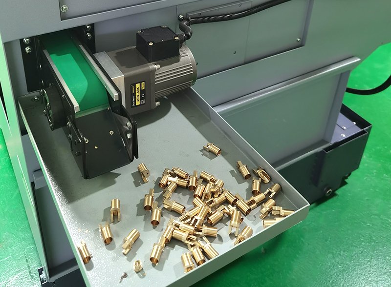
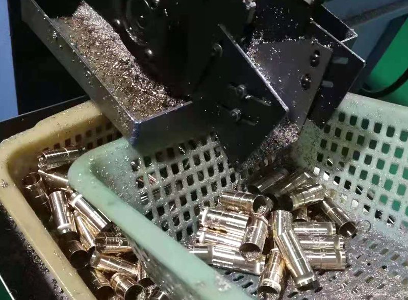
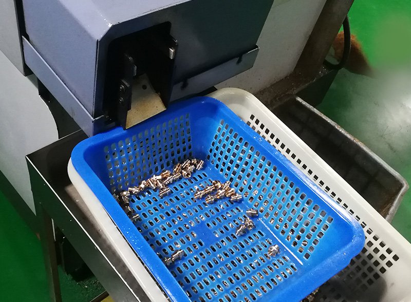
the manufacturing process directly determine the performance and reliability of the connector. High-precision stamping and injection molding are the two core technologies of modern connector manufacturing. The stamping accuracy of the contact is usually required to reach the micron level to ensure a tight fit of the contact interface; while the injection molding of the insulator requires strict control of the melt temperature, pressure and cooling rate to avoid defects such as flash, shrinkage and internal stress. As the trend of connector miniaturization continues, the requirements for manufacturing accuracy continue to increase. The key dimensional tolerances of some micro connectors have been reduced to within ±0.01mm, which places extremely high demands on mold design, processing equipment and process control. In addition, the assembly process is equally important, especially the automatic assembly of high-density connectors with multiple pins, which requires precise positioning systems and quality control methods to ensure that each contact is correctly positioned and maintains appropriate contact pressure.
The protection process is essential to improve the environmental adaptability and service life of the connector. Sealing technology is the core of the protection process, including rubber gasket sealing, potting sealing and hermetic sealing. Waterproof connectors usually use a multi-layer sealing design, such as a silicone rubber seal combined with waterproof glue filling, to achieve IP67 or higher levels of protection. Hermetic connectors use glass-to-metal or ceramic-to-metal sealing technology to completely isolate gas and liquid penetration, and are suitable for high vacuum and high pressure environments, such as aerospace and deep-sea equipment. Surface treatment processes such as anodizing, passivation and special coatings can significantly improve the corrosion resistance and wear resistance of the connector housing and extend the service life of the product in harsh environments. Although these protection processes increase manufacturing costs, for application scenarios that require high reliability and long life, such investment is often necessary and worthwhile.
Table: Performance comparison of common connector materials
| Material Type | Representative Materials | Temperature range | Key Benefits | Typical Applications |
| Contact material | Phosphor Bronze | -65~105℃ | Good elasticity and conductivity | Universal contact |
| Beryllium Copper | -200~150℃ | High strength and high elasticity | High reliability contacts | |
| Insulation Materials | PBT+GF | -40~200℃ | Good overall performance and low cost | Industrial Connectors |
| LCP | -50~320℃ | High temperature resistance, dimensionally stable | High temperature and high density connectors | |
| Housing Material | Aluminum Alloy | -60~125℃ | High strength, good shielding | Military and aviation connectors |
| Reinforced nylon | -40~105℃ | Lightweight, corrosion-resistant | Automotive Electronic Connectors |
Professional testing and verification: ensuring connector performance is flawless
The performance parameters of the connector need to be confirmed through systematic testing and verification, especially in high-reliability application scenarios. A comprehensive testing process is a necessary step to ensure that the connector meets the stringent requirements of use. Testing can not only verify the compliance of product specifications, but also discover potential design defects and process problems, providing an objective basis for selection decisions. Appearance inspection is the first step in connector testing and the most basic quality control link. Through visual inspection and magnifying glass inspection, the overall structural integrity of the connector, the quality of part assembly, and the surface treatment condition can be evaluated. The specific inspection content includes whether the contact parts are arranged neatly, whether the insulator has flash or burrs, and whether the shell is deformed or scratched. Although the appearance inspection is simple, it can find many potential problems, such as dimensional deviation caused by mold wear, surface defects caused by poor electroplating, or part misalignment caused by assembly errors. In high-end connectors such as aviation plugs, special attention should be paid to the matching accuracy of pins and sockets to ensure that the contact pairs can be correctly aligned and maintain appropriate contact pressure.
Electrical testing is a key step in verifying the conductive and insulating properties of connectors, and usually includes contact resistance testing, insulation resistance testing, and withstand voltage testing. The contact resistance test should use the four-wire method (Kelvin method) to eliminate the influence of the test cable resistance and ensure measurement accuracy. For small signal applications, a low-level contact resistance test (open circuit electromotive force ≤ 20mV, test current ≤ 100mA) is also required to evaluate the influence of the contact interface film resistance. This method can detect minor contact problems that traditional milliohm meters cannot find. The insulation resistance test applies a specified voltage (usually 100V, 250V or 500V DC) between mutually insulated contact pairs or between the contact pairs and the housing, and measures their resistance value. Commercial connectors generally require insulation resistance to reach 1000MΩ or more. The withstand voltage test verifies the connector’s ability to resist voltage breakdown. The test voltage is generally 1.5-3 times the rated voltage, and the duration is 1 minute. No breakdown or arcing should occur during the test. These electrical tests need to be performed not only in the initial state, but also repeatedly after environmental tests and mechanical durability tests to evaluate the performance changes of the connector after long-term use.
Mechanical testing mainly evaluates the structural strength and durability of the connector, including plug-in force testing, mechanical life testing, vibration and shock testing, etc. The plug-in force test measures the force change curve of the connector during the plug-in and disconnection process. It should not be too large to cause operational difficulties, nor too small to affect contact reliability. The mechanical life test simulates the plug-in and pull-out operations in actual use. Usually, 500-10,000 plug-in and pull-out cycles are performed to evaluate the performance changes of the connector. High-reliability connectors may require up to 25,000 plug-in and pull-out lives. Vibration and shock testing verifies the performance stability of the connector under dynamic mechanical stress, especially the continuity of contact resistance. During the test, it is necessary to monitor the electrical continuity of the contact pair and record the transient disconnection time (usually required to be no more than 1μs), which is particularly important for aerospace and automotive applications. In addition, special mechanical tests may be required for specific applications, such as lateral force testing of fiber optic connectors, shear force testing of board-to-board connectors, or torque testing of power connectors. These customized tests can better simulate actual use conditions and discover potential problems.
Environmental testing evaluates the performance of connectors under various extreme environmental conditions and is an important means of verifying the environmental adaptability of products. The temperature cycle test exposes the connector alternately to high temperature (such as +125℃) and low temperature (such as -55℃) environments to evaluate the impact of temperature changes on electrical and mechanical properties. The wet heat test is carried out in a high humidity environment (such as relative humidity above 95%, temperature 40-65℃), and the exposure time can reach 96 hours or even longer to evaluate the hygroscopicity of the insulating material and the corrosion resistance of the contact parts. The salt spray test simulates corrosive environments such as marine or road deicing salts. Usually, a 5% sodium chloride solution is used for continuous spraying for 96 hours. The change in contact resistance after the test should not exceed the specified value. For outdoor applications, UV aging tests and chemical resistance tests are also necessary. These tests can evaluate the performance changes of the connector housing and insulating materials after long-term environmental exposure. Hermetic connectors also need to undergo helium mass spectrometry leak testing to ensure that their sealing performance meets the requirements of high vacuum or high pressure environments.
Electromagnetic compatibility (EMC) testing is increasingly important for connectors used in modern electronic devices, especially for high-speed data communications and sensitive analog signal applications. Radiated emission testing evaluates the level of electromagnetic interference generated by connectors and their associated cables, while radiated immunity testing verifies the ability of connectors to maintain normal functions under strong electromagnetic field interference. Conducted emission and immunity testing evaluates the filtering and shielding effectiveness of connectors through power or signal cables. The transfer impedance test of shielded connectors is an important indicator to measure their shielding effectiveness. Low transfer impedance (<100mΩ/m) means better high-frequency interference suppression. In RF connectors, voltage standing wave ratio (VSWR) and insertion loss tests directly reflect the signal transmission quality. VSWR should be as close to 1:1 as possible, while insertion loss should be controlled within the system budget. These EMC tests require professional test equipment and environments, such as anechoic chambers, GTEM chambers or shielded rooms, and the test results directly affect the applicability of connectors in sensitive electronic systems.
Application simulation testing is the verification method that best reflects the actual performance of connectors. It comprehensively evaluates connectors by simulating real working conditions. Current cycle testing simulates the temperature rise and thermal cycle effects under actual working current (including steady-state current and transient shock) to evaluate the long-term reliability of connectors. Mixed signal testing applies power and signal at the same time to evaluate the crosstalk and interference between different circuits, especially the impact of adjacent contacts in high-density connectors. Mechanical environment composite testing combines vibration, shock and electrical load to simulate the use conditions in harsh environments such as vehicles and aviation. Although this type of test is complex, it can find many problems that cannot be exposed by a single test. For specific industry applications, special certification tests are also required, such as the full set of test items specified by standards such as AEC-Q100 for automotive electronics, DO-160 for avionics, or EN 50155 for railway electronics. Although these application simulation tests and certifications increase development costs and time, they are necessary investments to ensure long-term stable operation of products for high-reliability applications.
Table: Main test items and standards for connectors
| Test Category | Main test items | Common standards | Key Metrics |
| Electrical Testing | Contact resistance, insulation resistance, withstand voltage | IEC 60512 | Contact resistance ≤ 20mΩ, insulation resistance ≥ 1000MΩ |
| Mechanical Testing | Insertion force, mechanical life, vibration shock | MIL-STD-1344 | Plugging and unplugging times ≥ 500 times, instantaneous disconnection < 1μs |
| Environmental Testing | Temperature cycling, humidity, and salt spray | IEC 60068 | Temperature range -55~+125℃ |
| EMC Testing | Radiated emissions, shielding effectiveness, VSWR | CISPR 32, MIL-STD-461 | Transfer impedance <100mΩ/m |
| Application Testing | Current loop, mixed signal, complex environment | Industry-specific standards | Customized according to application requirements |
Application scenarios and selection examples: Connector selection strategy from theory to practice
The final choice of connector must return to the specific application scenario. The performance requirements, environmental adaptability and reliability standards of connectors in different fields vary significantly. By analyzing the special requirements of typical application scenarios, engineers can quickly identify key parameters and make the best choice among many options. Aerospace and defense applications represent the most demanding connector technologies, often requiring extreme environmental resistance, ultra-high reliability, and long life. In the selection of aviation plugs, voltage level selection is the primary consideration. The appropriate voltage rating must be determined based on the operating voltage of the aircraft electrical system (low voltage below 200V, medium voltage 200-1000V, high voltage above 1000V). The choice of protection level is also critical. External connectors on the fuselage need at least IP67 protection level to withstand rain and ice, while connectors near the engine compartment may require IP69K to withstand high-pressure cleaning and oily environments. In terms of materials, aluminum alloy shell combined with glass fiber insulation is a common choice, which can not only meet the lightweight requirements but also withstand extreme temperature changes from -65°C to +200°C. The preferred connection method is threaded locking or bayonet type to ensure a stable connection in a high vibration environment. For example, the MIL-DTL-38999 series connectors are widely used in the aerospace field. In addition, hermetic connectors are essential for high-altitude low-pressure environments to prevent degradation of insulation performance due to reduced air pressure.
industrial automation equipment face multiple challenges such as vibration, dust, humidity, and electromagnetic interference, and the convenience of frequent plugging and unplugging also needs to be considered. In factory automation systems, M8 and M12 circular connectors have become standard interfaces for sensors and actuators. Their compact threaded connection design provides IP67 protection level, meeting the needs of most industrial environments. For applications such as industrial robots that require flexible cables, high bending life connectors are a necessary choice. These products use special stress relief designs and bend-resistant cables that can withstand millions of bending cycles. Industrial Ethernet connectors need to consider both data transmission rates (such as 100Mbps or 1Gbps) and shielding effectiveness. They usually use RJ45 with metal shells or special industrial Ethernet connectors (such as X-coded M12) to ensure stable transmission in strong electromagnetic interference environments. In the field of process automation, explosion-proof connectors (compliant with ATEX or IECEx standards) are essential for applications in hazardous areas such as chemicals, oil and gas. These products use special designs to prevent internal sparks from causing explosions.
Automotive electronic connectors face harsh environments such as temperature fluctuations, vibration, and liquid exposure, while also meeting automotive industry-specific cost and quality standards. The selection of automotive connectors must first determine the application location – connectors in the engine compartment need to withstand high temperature environments of -40°C to +150°C, while connectors in the passenger compartment typically operate in a temperature range of -40°C to +85°C. Vibration requirements are also key in the selection of automotive connectors, especially connectors mounted on the engine or chassis, which must be able to withstand random vibrations of up to 30g in the frequency range of 10-2000Hz. FAKRA and Mini-FAKRA RF connectors have become standard interfaces for automotive infotainment systems and camera modules, while HSD (High-Speed Data) connectors support in-vehicle high-speed data networks. Electric vehicle high-voltage connectors are another important category, which need to meet operating voltages of 60V to 1000V and current requirements of up to 500A, while also having high-voltage interlock (HVIL) and touch-safe designs. The selection of automotive connectors must also consider the needs of automated assembly, such as secondary locking mechanisms such as CPA (Connector Position Assurance) and TPA (Terminal Position Assurance) to ensure consistent assembly quality under mass production conditions.
consumer electronics connectors emphasize miniaturization, lightness, and low cost. The USB Type-C connector has become a universal interface for smartphones, tablets, and laptops. Its 24-pin high-density design supports data transmission up to 40Gbps (USB4), 100W power transmission (USB PD), and DisplayPort video output. In wearable devices, ultra-thin board-to-board connectors and FPC connectors are widely used due to their ultra-low height below 0.3mm and lightweight characteristics. The plug-in and unplug life of consumer electronics connectors is usually designed to be 1000-5000 times, which is much lower than that of industrial or military connectors, but must meet the lead-free soldering process requirements and RoHS environmental protection directives. Anti-misplugging design is particularly important in consumer electronics connectors, and asymmetric structures or keyway designs are used to prevent users from connecting incorrectly and causing damage. With the increasing demand for waterproofing of consumer electronic products, IP67/IP68 waterproof connectors are also becoming more popular, such as headphone sockets and charging interfaces that use technologies such as silicone sealing and nano-coating.
Medical device connectors face unique challenges, including requirements for sterilization tolerance, reliability, and biocompatibility. Medical-grade connectors are often required to withstand multiple high-temperature, high-pressure steam sterilization (134°C, 200kPa) or ethylene oxide gas sterilization without performance degradation. In medical cable connectors, stress relief and anti-bending design are critical to extend service life, especially for applications that require frequent movement and bending, such as ultrasound probes and endoscopes. Electromagnetic compatibility is particularly important in medical devices, especially life-sustaining devices, which must use connectors with excellent shielding performance to prevent electromagnetic interference from affecting device functions. Medical power connectors usually use unique plug shapes and color coding to prevent safety hazards caused by misconnection, such as the requirements for medical electrical equipment connectors specified in the IEC 60601-1 standard. In implantable medical devices, connectors also need to consider biocompatibility and long-term stability, and biocompatible materials such as titanium alloys or medical-grade PEEK are usually used.
the energy and infrastructure fields need to cope with the dual challenges of harsh outdoor environments and long-term stable operation. In solar power generation systems, MC4 photovoltaic connectors have become the industry standard. Their IP67 protection level and 1000V/30A load capacity meet the needs of most photovoltaic modules. Connectors in wind power generation equipment need to pay special attention to vibration resistance and weather resistance, especially connectors installed in the nacelle and blades, which must be able to withstand temperature changes from -40°C to +85°C and continuous vibration caused by strong winds. Charging pile high-voltage connectors are key components of electric vehicle infrastructure. They need to meet working conditions of up to 1000V DC and 250A, and have safety functions such as interlocking, temperature monitoring and anti-electric shock protection. In industrial power systems, Anderson power connectors have become the first choice for battery and power distribution systems due to their high current carrying capacity (up to 350A) and convenient plug-in and unplug operations. These energy infrastructure connectors usually require a service life of more than 10 years and extremely high reliability, so when selecting, special attention should be paid to material aging characteristics and the supplier’s long-term supply capabilities.
As the “nerve node” of the electronic system, the selection process of the connector needs to balance the three factors of performance, environment and cost. In the actual selection process, it is recommended to adopt a systematic approach: first clearly define the application requirements and the use environment; then determine the key performance parameters and interface standards; then evaluate the mechanical constraints and installation requirements; then consider the environmental adaptability and reliability requirements; finally balance the cost and supply chain factors. Throughout the selection process, close communication with the supplier’s technical team is essential, especially for non-standard or special application scenarios, customized solutions may be the best choice. With the continuous development of connector technology, new materials, new processes and new designs will continue to emerge. Engineers need to keep an eye on industry trends, keep abreast of the latest technical solutions, and choose the most suitable connector products for the project.