You need to understand terminal connector pinouts before you select a 4-pin male connector for your project. Each connector assigns a specific function to every pin, such as power, ground, or data. You can quickly check compatibility by comparing the pin arrangement on your connector with your device’s requirements. Always verify the pin layout, whether you use an M8 connector, Type B connector, or other connectors from a Connector factory. Proper identification prevents damage and ensures safe terminal connections.
Tip: Always match the pin numbers on your connectors to your device’s specifications to avoid wiring errors.
What is a 4-Pin Male Terminal Connector?
Basic Description and Features
Physical Characteristics
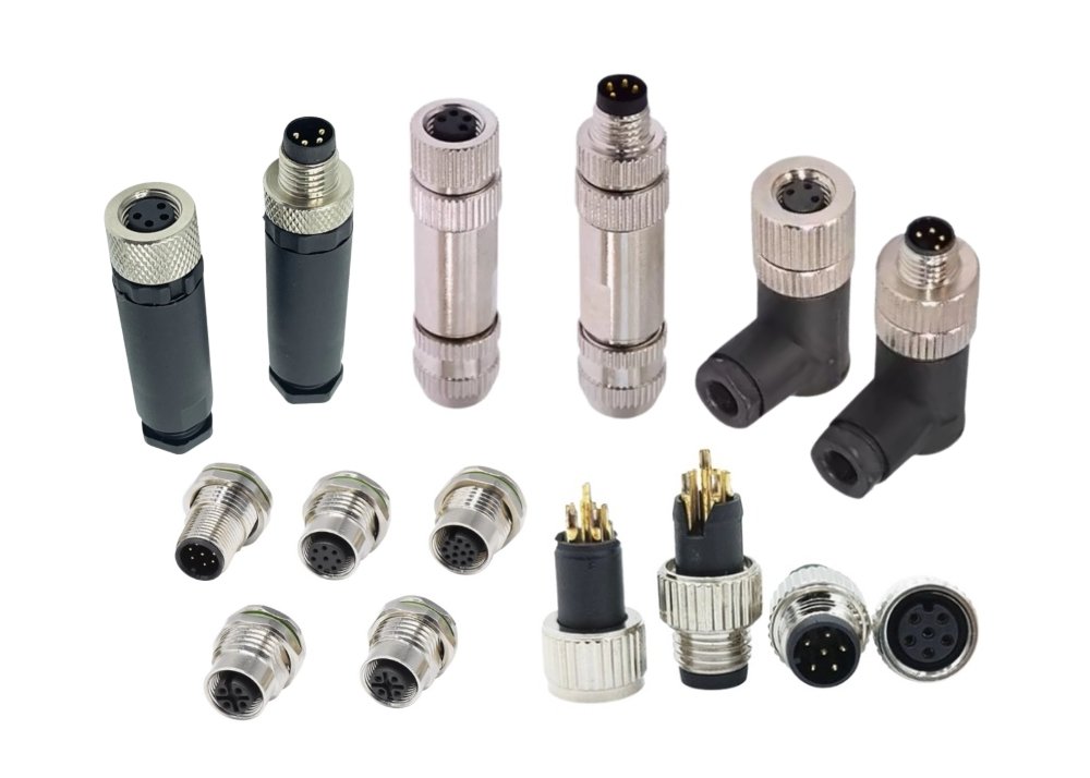
You encounter 4-pin male terminal connectors in many electronic and industrial systems. These connectors feature four metal pins arranged in a single row or square pattern. Each pin serves a specific function, such as carrying power, ground, or data signals. The male connector has exposed pins that insert into a matching female socket. You often see these connectors made from durable plastics and metals to ensure a secure fit and reliable electrical contact. The compact design allows you to use them in tight spaces, making them ideal for modern devices.
Male vs. Female Configurations
You need to distinguish between male and female configurations when selecting connectors. The male connector has protruding pins, while the female connector contains sockets that receive these pins. You use male connectors to plug into devices or circuit boards, while female connectors remain fixed on the equipment. This distinction helps you avoid mismatched connector types, which can lead to compatibility issues or connection failures.
Common Applications
Computing and Power Supply Uses
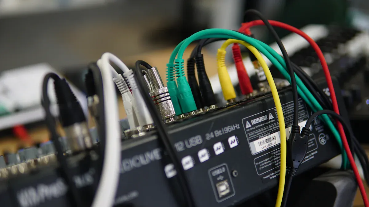
You find 4-pin connectors in computing systems, especially for power supply connectors. These connectors link power supplies to motherboards and peripherals, ensuring stable operation. You also see them in USB connectors, including usb-a connectors and usb-b connectors, where they transmit both power and data. Many laptops, smartphones, and digital cameras rely on these connectors to connect printed circuit boards and modules. You use jst connectors and jst connector types for battery packs and remote controls in consumer electronics.
Industrial and Automotive Uses
You rely on 4-pin connectors in industrial automation and automotive electronics. These connectors provide robust connections for sensors, control circuits, and lighting assemblies. You see them in robots that manufacture semiconductor chips, as well as in smart home technology like security cameras and smart lighting controls. The versatility of these connectors allows you to use them in air conditioners, refrigerators, and washing machines.
- Automotive systems: Used in lighting assemblies, sensor modules, and infotainment systems.
- Computer systems: Connect power supplies to motherboards and peripherals.
- Smart home technology: Found in security cameras and smart lighting controls.
| Application Type | Examples |
|---|---|
| Household Appliances | Air conditioners, refrigerators, washing machines |
| LED Lighting | Power and control connections for LED strips |
| Consumer Electronics | Battery packs, remote controls |
You benefit from the reliability and compactness of 4-pin connectors, which balance versatility and performance across many applications.
Visual Identification
Pin Arrangement Patterns
You identify 4-pin connectors by their pin arrangement. Most connectors display pins in a straight line or a square configuration. You must check the orientation and spacing to ensure compatibility with your device. USB connectors, including usb-a connectors and usb-b connectors, have standardized pin layouts, making identification easier. You also see unique patterns in jst connectors, which require careful inspection.
Connector Size and Pitch
You need to consider connector size and pitch when selecting the right component. Pitch refers to the distance between adjacent pins. Standard pitches help you match connectors to circuit boards and cables. Improper sizing can lead to installation difficulties and connection failures. You should always verify the fit before making a final selection.
Tip: Always check the connector’s locking mechanism and contact material to prevent loose connections and corrosion.
Standard Terminal Connector Pinouts for 4-Pin Connectors
When you work with 4-pin connectors, you must understand the standard terminal connector pinouts to ensure safe and reliable connections. Each connector assigns specific functions to its pins, and these assignments vary depending on the application and standard.
Common Pinout Standards
Molex 4-Pin Power Pinouts
You often encounter Molex connectors in computer systems, especially for power supply connections. The Molex 4-pin connector provides a straightforward layout for power distribution. You use these connectors to deliver voltage and ground to devices like hard drives and fans. The pin arrangement typically follows a standard pattern, which helps you avoid wiring mistakes.
| Pin Number | Function |
|---|---|
| 1 | +V (Positive Voltage Supply) |
| 2 | Signal/Data |
| 3 | 0 V (Ground) |
| 4 | Signal/Data |
This table shows a recognized international standard for 4-pin terminal connector pinouts. You should always verify the pin assignments before connecting to prevent damage.
M12 A-Coded and D-Coded Pinouts
You find M12 connectors in industrial automation and sensor systems. The A-coded version supports power and signal transmission, while the D-coded version focuses on Ethernet and data communication. You must check the coding type because the pinouts differ between A-coded and D-coded connectors. M12 connectors provide robust connections for harsh environments, and you rely on their secure locking mechanisms.
Automotive 4-Pin Pinouts
You use automotive 4-pin connectors in lighting assemblies, sensor modules, and infotainment systems. The pinouts in automotive applications often follow manufacturer-specific standards. You must consult the vehicle’s documentation to confirm the correct pin assignments. Using non-standard pinouts in automotive connectors can lead to electric shock, electrical shorts, overheating, and even legal issues due to non-compliance with safety codes. You should never assume compatibility based on appearance alone.
Tip: Always match the connector terminal pins to the wiring diagram provided by the manufacturer to avoid costly mistakes.
Pinouts for Power, Ground, and Data
Power and Ground Assignments
You need to identify which pins carry power and ground in your connector. Most standard 4-pin connectors assign one pin for positive voltage (VCC) and another for ground (GND). This assignment ensures stable operation and prevents electrical faults.
| Pin Number | Label | Description |
|---|---|---|
| 1 | VCC | Power supply (positive voltage) |
| 2 | GND | Ground (negative voltage) |
| 3 | DATA | Data signal or control signal |
| 4 | CLK | Clock signal (if used in communication) |
You see this configuration in many usb connectors, jst connectors, and even in the atx 24 pin main power cable connector. You must confirm the pinouts before wiring to avoid reversed polarity or short circuits.
Data and Signal Pinouts
You use the remaining pins for data and signal transmission. In usb-a connectors and other usb connectors, these pins handle communication between devices. You find similar arrangements in jst connector types, where data and clock signals enable precise control. You must ensure that the data and signal pins match the device’s requirements, especially when connecting to printed circuit boards or modules.
Manufacturer-Specific Pinouts
Variations in Pin Arrangement
You notice that not all connectors follow the same pinout standards. Manufacturers may alter the arrangement of pins to suit specific applications. You see this in custom usb connectors, jst connector designs, and specialized industrial connectors. You must inspect the connector and compare it to the datasheet to avoid mismatched connections.
Importance of Checking Documentation
You should always consult the manufacturer’s documentation before making any connections. The datasheet provides detailed diagrams of the connector pinouts, including the function of each pin. You reduce the risk of electric shock, electrical shorts, overheating, and damage to your equipment by following the correct pin assignments. Non-standard pinouts can cause serious hazards, including arcing and fire, especially in automotive and industrial systems.
Note: Never rely solely on visual inspection. Always verify the pinouts using official documentation and testing tools.
You improve safety and reliability by understanding the terminal connector pinouts and following best practices. You protect your devices and systems from costly failures and ensure compliance with industry standards.
How to Identify Your Connector’s Pinouts

Correctly identifying the pinouts of your 4-pin male connector is essential for safe and reliable connections. You can use several methods to determine the function of each pin, from reading labels to testing with a multimeter. This section guides you through each step, ensuring you avoid costly mistakes and protect your devices.
Labeling and Markings
Reading Connector Labels
Manufacturers often print or engrave labels directly on the connector. You should look for numbers, symbols, or color codes next to each pin. These markings help you match each pin to its function, such as power, ground, or data. For example, many usb connectors display a small diagram or numbering system on the housing. You can use these labels to quickly identify the correct orientation before making a connection.
Tip: Always inspect both sides of the connector. Some labels appear only on one side or may be hidden by dust or debris.
Identifying Pin Numbers and Orientation
You need to determine the orientation of the connector before connecting it to your device. Most connectors use a notch, key, or flat edge to indicate the correct alignment. You should match the pin numbers on the connector to the corresponding numbers on your device or circuit board. For usb connectors, the wider side usually faces up, while jst connectors often include a small arrow or indentation. Always double-check the orientation to prevent reversed connections, which can damage sensitive components.
Using Datasheets and Documentation
Locating Manufacturer Datasheets
You can find the most accurate information about your connector in the manufacturer’s datasheet. These documents provide detailed diagrams, pin assignments, and technical specifications. You should search for the part number printed on the connector or packaging. Most manufacturers offer datasheets on their websites or through authorized distributors. Once you locate the datasheet, you gain access to essential details for safe wiring.
Interpreting Pinout Diagrams
Datasheets usually include a pinout diagram or table that shows the function of each pin. You should follow these best practices when reading pinout diagrams:
- Find the Pinout Diagram: Locate the diagram or table for your specific connector model in the datasheet.
- Study the Pin Layout: Review the layout, including pin numbers and names, often shown in a grid or schematic.
- Understand the Pin Functions: Read the descriptions for each pin, such as input, output, ground, or power.
- Examine the Pin Connections: Check how each pin connects to other components or devices.
- Check the Datasheet for Clarification: Refer to the datasheet for explanations of unfamiliar terms or symbols.
You often see pinout tables like the one below in datasheets:
| Pin Name | Description | Function |
|---|---|---|
| 1 | Pin 1 | Function 1 |
| 2 | Pin 2 | Function 2 |
| 3 | Pin 3 | Function 3 |
| 4 | Pin 4 | Function 4 |
You can also use the datasheet to identify pin connections and measure resistance between pins with an ohmmeter. This helps you confirm which pins are connected internally.
Testing Pinouts with a Multimeter
Continuity Testing Steps
You should always verify pinouts with a multimeter before making any connections. This tool helps you check for electrical continuity and ensures each pin performs its intended function. Follow these steps for accurate testing:
- Set your multimeter to continuity mode (often called ‘beeper mode’).
- Connect one lead of the multimeter to the wire you want to identify.
- Use the other lead to touch one of the pins in the connector, making sure not to touch other pins.
- Repeat the process for each pin until the multimeter beeps, then mark the identified wire.
This method works well for usb connectors, jst connector types, and other 4-pin connectors. You can quickly map out which wire connects to each pin.
Voltage and Signal Verification
After confirming continuity, you should check for correct voltage and signal flow. Set your multimeter to the appropriate voltage or resistance setting. Measure between the power and ground pins to verify the expected voltage. For data pins, you can check for signal presence by measuring voltage changes when the device operates. Always use a magnifying glass to inspect pins for damage or corrosion before testing. You can also use contact cleaner to remove debris and restore conductivity.
Note: For advanced testing, you can perform an intermittence test by flexing the connector while sending test pulses. This helps you detect hidden faults or weak connections.
You ensure safe and reliable connections by following these steps. Proper identification of terminal connector pinouts protects your equipment and supports stable operation in usb, jst, and other connector systems.
Compatibility Considerations for 4-Pin Male Connectors
Matching Pinouts to Devices and Systems
Cross-Referencing Pin Functions
You must cross-reference pin functions when connecting a 4-pin male connector to any device. Each pin in the connector serves a unique purpose, such as power, ground, or data transmission. You should compare the terminal connector pinouts from your device’s documentation with the connector’s datasheet. This step helps you avoid mismatches that could damage sensitive electronics. For example, when working with usb connectors or jst connector types, you need to ensure that the power and data pins align with the device’s requirements.
| Key Factors | Description |
|---|---|
| Voltage and Current Ratings | Ensure the connector can handle the required power for the device. |
| Physical Design and Pin Functions | Match the connector’s design and pin layout to the device’s requirements. |
| Reliability and Durability | Choose connectors that can withstand environmental challenges, such as vibration and moisture. |
You should always verify the voltage and current ratings before using power supply connectors or atx power housing connectors. This practice prevents overheating and electrical faults.
Checking Connector Orientation and Pitch
You need to check the orientation and pitch of the connector before installation. The pitch refers to the distance between adjacent pins. Many usb connectors and power connectors use standardized pitches, but some devices require unique spacing. You should inspect the connector’s keying features, such as notches or flat edges, to ensure proper alignment. Incorrect orientation can lead to reversed connections, which may cause short circuits or data loss. Always confirm that the connector fits securely into the terminal or device socket.
Common Compatibility Pitfalls
Mismatched Power and Ground Connections
You may encounter issues if you connect the power and ground pins incorrectly. This mistake can result in device failure or even fire hazards. Manufacturers often warn against mixing connectors from different sources, especially when using 4.2mm pitch connectors. You should avoid assuming compatibility based on appearance alone. Always consult the wiring diagram and verify each pin’s function before connecting.
Swapped Data or Signal Lines
Swapping data or signal pins is another frequent problem. You might notice unstable data transmission or complete communication failure if the usb or jst connector pins do not match the device’s pinouts. Device diversity and evolving standards complicate universal connector design. You should pay close attention to the pin assignments for usb connectors, especially when working with multi-device environments.
| Compatibility Issue Type | Description |
|---|---|
| Standardization Issues | Evolving standards lead to compatibility challenges between old and new devices, affecting connectors. |
| Device Diversity | A variety of devices require different connector shapes and sizes, complicating universal design. |
| Electrical Signal Interference | Interference in multi-device environments can affect signal integrity and data transmission stability. |
- The reliance on compatibility of 4.2mm pitch connectors across manufacturers can lead to undocumented compatibility issues.
- Manufacturers often advise against mating connectors from different sources, raising concerns about reliability.
- The common practice of using connectors from various manufacturers may result in failures if not properly managed.
Safety Tips for Wiring and Connections
Preventing Short Circuits
You must take precautions to prevent short circuits when wiring connectors. Always de-energize circuits before installation. Use insulated tools designed for electrical work. Wear personal protective equipment, such as gloves and safety glasses. You should match the wire gauge to the connector and verify load compatibility to avoid electrical faults. Assess environmental conditions, including moisture and vibration, which may affect connector performance.
Electrical safety is paramount. The U.S. Bureau of Labor Statistics reported 145 worker deaths and nearly 3,000 injuries from electrical exposure in 2022. You must adhere to safety standards during installations to protect yourself and your equipment.
Double-Checking Pinouts Before Use
You should always double-check pinouts before using a connector in a new application. Review the datasheet, inspect the connector’s markings, and test each pin with a multimeter. Confirm that the power, ground, and data pins match the device’s requirements. This step helps you avoid costly mistakes and ensures reliable operation for usb, jst, and power connectors.
Examples of Compatible and Incompatible Pinouts
Real-World Compatible Connection Scenarios
Power Supply to Device Pinouts
You often see successful connections when you match the pinouts of your connector to the device’s requirements. The JST SM Male Connector 4 Pin is a popular choice in LED lighting systems. You use this connector to deliver power and control signals to LED strips, ensuring stable illumination. In RC vehicles, you rely on the same connector for battery and motor connections. The pins provide reliable contact, which helps prevent power loss during operation. You also find this connector in electronic devices that demand secure and consistent connections.
- You connect a JSN-SR04T Ultrasonic Sensor to a Raspberry Pi 4B using a 4-pin male connector. The pins transmit power, ground, and data signals, allowing accurate distance measurement.
- You use atx power housing connectors in computer systems to supply power to motherboards and peripherals. The connector’s pins ensure proper voltage delivery and prevent electrical faults.
Data Communication Pinouts
You achieve reliable data transmission when you use connectors with standardized pinouts. USB connectors are common in many devices, including printers, cameras, and external drives. The pins in these connectors carry both power and data signals. You benefit from consistent communication and minimal signal loss. When you use USB connectors for charging and data transfer, you avoid compatibility issues by following the manufacturer’s pinout diagrams.
- You connect USB devices to your computer using 4-pin male connectors. The pins handle power, ground, and two data lines, supporting fast and stable data exchange.
- You integrate connectors into smart home systems, where the pins transmit control and data signals between sensors and controllers.
Troubleshooting Incompatible Pinouts
Identifying Symptoms of Pinout Mismatch
You may encounter problems if the connector’s pinouts do not match the device’s requirements. Common symptoms include:
- Intermittent electrical failures, such as flickering lights or malfunctioning components.
- Visible damage, including cracks, corrosion, or bent pins in the connector.
- Loose fit, which indicates the connector is not properly seated.
- Unusual odors or heat, such as burnt plastic or excessive warmth, suggesting electrical shorts.
Tip: Always inspect your connectors for physical damage and test for proper fit before making any connections.
Steps to Resolve Pinout Issues
You can resolve pinout problems by following a systematic approach:
- Clean the connector using contact cleaner and a soft brush to remove dirt and oxidation from the pins.
- Test the connection with a multimeter to check for proper power delivery and continuity between pins.
- Secure the fit by ensuring the connector is firmly in place. Replace any broken clips or damaged connectors.
- Inspect connectors for contamination, corrosion, or physical damage. Clean surfaces thoroughly.
- Reseat loose connections or replace faulty terminals as needed.
- Check connector pinouts and wiring diagrams. Fix any crossed connections or misplaced pins.
You maintain safe and reliable connections by following these steps. You prevent data loss and electrical hazards in USB, LED, and other electronic systems.
You can identify terminal connector pinouts accurately by following these steps:
- Examine the connector’s shape, color, and keyways.
- Count the pins and determine if the connector is a plug or receptacle.
- Check your manual and use online tools for matching terminal types.
- Trace wiring diagrams and look for labels.
- Practice reading diagrams regularly.
Always verify pinouts and compatibility before connecting. Use this checklist for safe and reliable connections:
- Inspect connector details and location.
- Consult datasheets.
- Test pinouts with a multimeter.
FAQ
What does “pinout” mean for a 4-pin connector?
Pinout refers to the specific assignment of each pin in your connector. You use pinouts to identify which pin carries power, ground, or data signals. Accurate pinout identification helps you avoid wiring mistakes.
How do you find the pinout for your connector?
You check the manufacturer’s datasheet or product documentation. You look for diagrams or tables that show each pin’s function. You can also use a multimeter to test continuity and verify pin assignments.
Can you use any 4-pin connector for power and data?
You must match the connector’s pinout and voltage rating to your device. Not all 4-pin connectors support both power and data. You risk damaging your equipment if you use incompatible connectors.
What tools help you test connector pinouts?
You use a digital multimeter for continuity and voltage checks. You may also use a magnifying glass to inspect pin labels. You rely on datasheets for reference during testing.
Why do manufacturers use different pinouts?
Manufacturers design connectors for specific applications. You see variations to meet unique requirements for power, data, or safety. Always check documentation before connecting unfamiliar connectors.
What happens if you connect pins incorrectly?
You may cause short circuits, device failure, or data loss. You should always double-check pin assignments before wiring. Incorrect connections can damage sensitive electronics.
How do you prevent corrosion on connector pins?
You keep connectors clean and dry. You use contact cleaner for maintenance. You store connectors in sealed containers when not in use. Regular inspection helps you spot early signs of corrosion.
Are 4-pin connectors standardized across industries?
You find some standards, like Molex or USB, but many connectors differ by manufacturer or application. You must verify pinouts and specifications for each connector to ensure compatibility.